
Lineup expansion of SiC SBDs of 650 V contributing to high efficiency of power supply PFCs : TRS12N65FB, TRS16N65FB, TRS20N65FB, TRS24N65FB
Product News 2020-07
Toshiba Electronic Devices & Storage Corporation ("Toshiba") has launched four 650 V Schottky Barrier Diode (SBD) products to expand its lineup : “TRS12N65FB,” “TRS16N65FB,” “TRS20N65FB,” and “TRS24N65FB” that use SiC (Silicon Carbide), a new material allowing higher efficiency of power supply PFCs (Power Factor Corrections). They use the TO-247 package and offer four forward DC current ratings (Both Legs) - 12 A, 16 A, 20 A, and 24 A - supporting increase of power of equipment.
The new products are Toshiba’s second-generation SiC SBDs with the improved JBS (Junction Barrier controlled Schottky) structure. They feature high surge current capability and low-loss characteristics, with a non-repetitive peak forward surge current rating (Per Leg) of 92 A[1], about 53 %[2] improvement, and typical forward voltage (Pre Leg) of 1.45 V, about 6 %[2] reduction compared with our first-generation products. These features allow higher efficiency and larger margins in thermal design of equipment.
Toshiba will expand lineup in the future and contribute to higher efficiency and downsizing of communications equipment, servers, inverters, and other products.
Notes :
[1] Case of TRS24N65FB
[2] TRS24N65FB is compared with TRS24N65D
Features
- High non-repetitive peak forward surge current ratings :
IFSM (Per Leg) / (Both Legs)=52 A / 104 A (TRS12N65FB)
IFSM (Per Leg) / (Both Legs)=65 A / 130 A (TRS16N65FB)
IFSM (Per Leg) / (Both Legs)=79 A / 158 A (TRS20N65FB)
IFSM (Per Leg) / (Both Legs)=92 A / 184 A (TRS24N65FB) - Low forward voltage :
VF (Per Leg)=1.45 V (typ.) @IF=6 A (TRS12N65FB)
VF (Per Leg)=1.45 V (typ.) @IF=8 A (TRS16N65FB)
VF (Per Leg)=1.45 V (typ.) @IF=10 A (TRS20N65FB)
VF (Per Leg)=1.45 V (typ.) @IF=12 A (TRS24N65FB)
Applications
- Power supplies for industrial equipment
(base stations, PC servers, power supplying facilities for electric vehicles and laser beam machines, etc.) - Power supplies for consumer equipment
(organic EL-TVs, audio amplifiers, projectors and multi-function printers, etc.
Product Specifications
(Unless otherwise specified, @Ta=25 °C)
| Part number | TRS12N65FB | TRS16N65FB | TRS20N65FB | TRS24N65FB | ||
|---|---|---|---|---|---|---|
| Packages | TO-247 | |||||
| Absolute maximum ratings |
Repetitive peak reverse voltage VRRM (V) |
650 | ||||
| Forward DC current IF(DC) (A) |
Both Legs |
12 | 16 | 20 | 24 | |
| Non-repetitive peak forward surge current IFSM (A) @t=10 ms |
Per Leg |
52 | 65 | 79 | 92 | |
| Both Legs |
104 | 130 | 158 | 184 | ||
| Junction temperature Tj (°C) |
175 | |||||
| Reverse current IR typ. (μA) @VR=650 V |
Per Leg |
0.3 | 0.4 | 0.5 | 0.6 | |
| Forward voltage VF typ. (V) |
Per Leg |
1.45 | ||||
| @IF (A) | 6 | 8 | 10 | 12 | ||
| Total junction capacitive charge Qcj typ. (nC) @VR=0.1 to 400 V |
Per Leg |
15 | 19.4 | 24 | 30 | |
| Thermal resistance (junction-to-case) Rth(j-c) max (°C/W) @Tc=25 °C |
Per Leg |
2.2 | 1.8 | 1.4 | 1.3 | |
| Both Legs |
1.1 | 0.9 | 0.7 | 0.65 | ||
Internal Circuit

Application Circuit Example
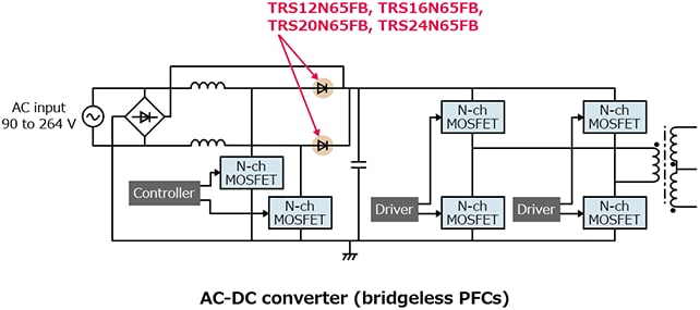
The application circuits shown in this document are provided for reference purposes only. Thorough evaluation is required, especially at the mass-production design stage. Providing these application circuit examples does not grant any license for industrial property rights.
Information in this document, including product prices and specifications, content of services and contact information, is correct on the date of the announcement but is subject to change without prior notice.