
A Novel BLDC Motor Initial Position Detection Technique for Increaseed Resolution to 15 Degree
Brushless DC (BLDC) motors and drives play an increasingly important role in industrial and commercial applications. This is due to their low inertia, high torque, and high-power density which result in overall highly efficient drives.
Unlike some other types of motors and drives, for successful and smooth startup, BLDC motor needs to know at least approximately, where the rotor permanent magnetic poles are relative to the stator coils so the driving magnetic fields can be properly aligned.
Too much misalignment between the electric magnetic pole generated by stator winding and the rotor permanent magnetic pole will cause a sluggish or failed motor startup. If the poles are off-phase, the motor might initially rotate in the reverse direction, which is unacceptable in many applications.
Traditionally, a position sensor, typically a HALL sensor or an encoder, is employed to measure and detect the rotor position. These additional components lead to higher cost and lower reliability. Recently, as sensorless techniques have been developed and become widely applied, the position sensors can be eliminated while still maintaining good BLDC motor operation at high speed. However, restricted by sensorless control working principle itself, the accuracy of detecting the rotor position at low speed is reduced and impossible to tell the rotor position at stand still unless special techniques are applied. This is where initial position detection (IPD) come into play.
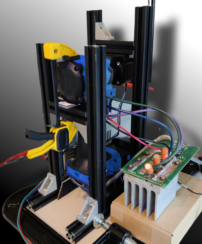
For a motor with a high saliency ratio, motor inductance varies with rotor position.. The change in the motor inductance value repeats periodically as a function of rotor position as shown the diagram below. This characteristic provides us a way to estimate the rotor position by measuring the motor inductance at the specific location. This characteristic is defined by motor design which can be measured and verified by a designed test. In our case, a test fixture was designed to use a stepper motor driven by Toshiba stepper drive, TB9120, to turn the rotor one revolution at a small step incrementally.
BLDC Motor Initial Position Detection
For a motor with a high saliency ratio, motor inductance varies with rotor position.. The change in the motor inductance value repeats periodically as a function of rotor position. This characteristic provides us a way to estimate the rotor position by measuring the motor inductance at the specific location. This characteristic is defined by motor design which can be measured and verified by a designed test. In our case, a test fixture was designed to use a stepper motor driven by Toshiba stepper drive, TB9120, to turn the rotor one revolution at a small step incrementally.
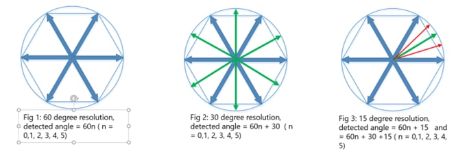
Initial position detection (IPD) techniques with 60 degree resolution are well-known. These are often based on using the peak among three phase currents to indicate approximate rotor positions at 0, 60, 120, …300 degrees across one revolution. This can be achieved by quickly turning on/off motor phases in a known sequence to generate phase current pulses and measuring the response. The magnitude of the measured phase current pulse is proportional to the inductance at the standstill position. The position is then estimated using the processed current pulse magnitude.
By first characterizing the magnetic properties of the motor with respect to rotor position, machine learning (ML) and data analysis tools can be applied to extract more information from the phase current pulse measurements making it possible to differentiate the rotor positions between the 60 degree positions. For example, the roughly 30 degree position between 0 and 60 degrees can be detected. With further enhancement, it is even possible to detect the 15 degree position between 0 and 30 degrees and the roughly 45 degree position between 30 and 60 degree and so on. The result is that 15 ± 7.5 degree resolution can be achieved without a position sensor.
A test fixture was designed to use a stepper motor driven by Toshiba’s TB9120AFTG stepper drive, With this it was possible to turn the motor incrementally with small steps and measure the magnetic characteristics for one full rotor revolution .
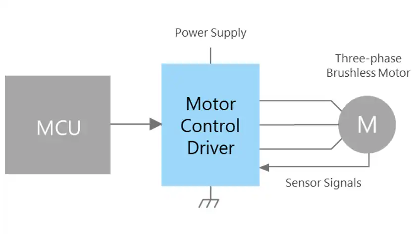
This technique was implemented on top of a proven 60 degree accuracy IPD algorithm and has been tested on Toshiba’s TMPM375FSDMG vector engine motor control MCU (VE-MCU ). Testing was done with a three-phase brushless motor driver circuit and verified on a power tool drill motor showing the target initial position detection resolutions can be achieved. In addition, it can be extended to Toshiba TX03/TXZ & TXZ+ series motor control VE-MCUs.
Recommended product for Three-phase Brushless Motor Drive
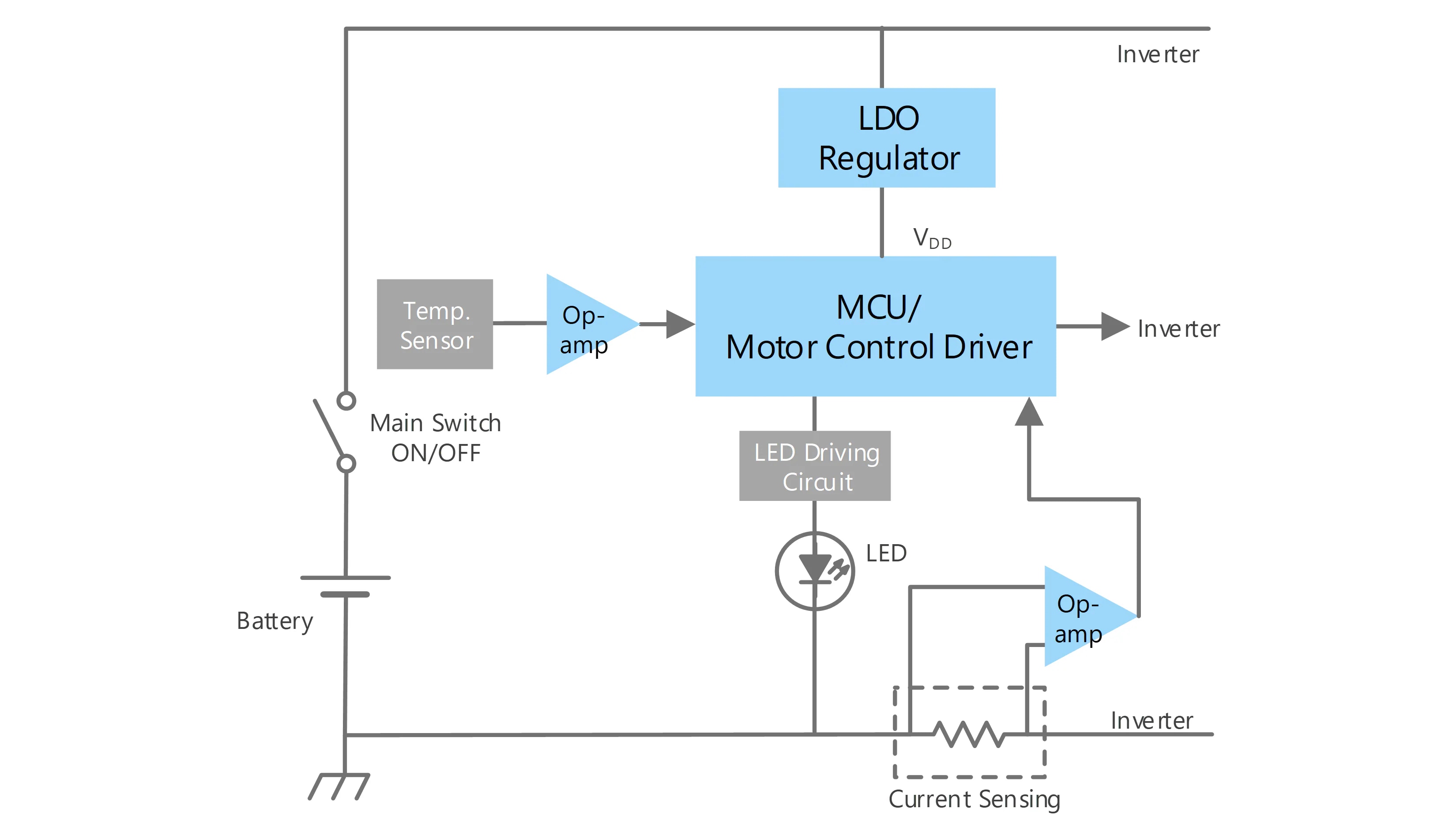
The set with low heat generation and low power consumption can be realized by using MOSFET with high dissipation efficiency and low on-resistance as a driver.
Product name |
Package (Width×Length×Height mm) |
Product Overview |
Checking On-line distributor inventory |
|---|---|---|---|
DSOP Advance
|
N-ch, VDSS=40V, ID=340A, RDS(ON)=0.8mO (Max)(@VGS=10V) |
|
|
SOP Advance
|
N-ch, VDSS=40V, ID=340A, RDS(ON)=0.85mO (Max)(@VGS=10V) |
|


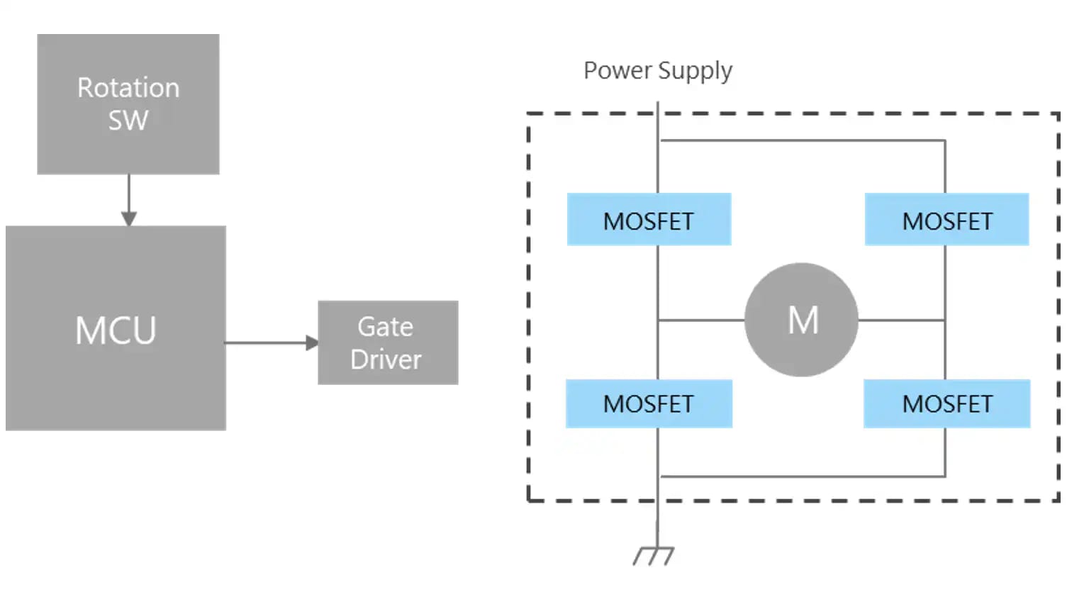
By using motor driver, one can easily drive a three-phase brushless motor using inverter control which is increasingly popular in recent years.
System can drive high capacity brushless motor by using motor controller with external MOSFET.
Product name |
Package (Width×Length×Height mm) |
Product Overview |
Checking On-line distributor inventory |
|---|---|---|---|
P-WQFN36-0505-0.50-001 |
3-Phase Brushless Motor control driver (w/MOSFET), VMopr=6 to 22V, IOUT(peak)=3A, VO=25V |
|
|
SSOP30-P-300-0.65 |
3-phase brushless motor controller, VCC=6 to 16.5V, IOUT(peak)=2mA, VO=18V |
|
Product name |
Package (Width×Length×Height mm) |
Overview |
Checking On-line distributor inventory |
|---|---|---|---|
SOT-23 (SOT23)
|
PNP, IC=-0.2A(Max), VCEO=-50V(Min), VCE(sat)=-0.25V(Max), hFE=300(Max) |
|
|
SOT-323 (USM)
|
NPN, IC=0.15A(Max), VCEO=50V(Min), VCE(sat)=0.25V(Max), hFE=700(Max) |
|


The set with low heat generation and low power consumption can be realized by using MOSFET with high dissipation efficiency and low on-resistance as a driver.
Product name |
Package (Width×Length×Height mm) |
Overview |
Checking On-line distributor inventory |
|---|---|---|---|
DSOP Advance
|
N-ch, VDSS=40V, ID=340A, RDS(ON)=0.8mO (Max)(@VGS=10V) |
|
|
SOP Advance
|
N-ch, VDSS=40V, ID=340A, RDS(ON)=0.85mO (Max)(@VGS=10V) |
|
Other block diagrams
Other Technical Content