
- General Top
- SEMICONDUCTOR
- STORAGE
- COMPANY
-
My ToshibaSemicon
- Semiconductor Top
-
ApplicationsAutomotive
Body Electronics
xEV
In-Vehicle Infotainment
Advanced Driver-Assistance Systems (ADAS)
Chassis
IndustrialInfrastructure
BEMS/HEMS
Factory Automation
Commercial Equipment
Consumer/PersonalIoT Equipment
Healthcare
Wearable Device
Mobile
Computer Peripherals
-
ProductsAutomotive Devices
Discrete Semiconductor
Diodes
Transistors
Logic ICs
Analog Devices
- Automotive SmartMCD™ (Integreted SoC Conbining Microcontroller and Driver)
- Automotive Brushless Motor Driver ICs
- Automotive Brushed DC Motor Driver ICs
- Automotive Stepping Motor Driver ICs
- Automotive Driver ICs
- Automotive System Power Supplies ICs
- Automotive audio power amplifier ICs
- Automotive Network Communication
Digital Devices
Wireless Devices
※
 : Products list (parametric search)Power Semiconductors
SiC Power Devices
※
: Products list (parametric search)Isolators/Solid State RelaysPhotocouplers
Digital Isolators
Solid State Relays
Fiber Optic Transmitting Modules
※
: Products list (parametric search)MOSFETsIGBTs/IEGTsBipolar Transistors※
: Products list (parametric search)Diodes※
: Products list (parametric search)MicrocontrollersMotor Driver ICsIntelligent Power ICs※
: Products list (parametric search)Power Management ICsLinear ICs※
: Products list (parametric search)General Purpose Logic ICsLinear Image SensorsOther Product ICsOther Product ICs
※
: Products list (parametric search) -
Design & Development
Design & Development
Innovation Centre
At the Toshiba Innovation Centre we constantly strive to inspire you with our technologies and solutions. Discover how to place us at the heart of your innovations.
-
Knowledge
Knowledge
Highlighted Topics
Further Materials
Other
- Where To Buy


- Part Number & Keyword Search
- Cross Reference Search
- Parametric Search
- Stock Check & Purchase
This webpage doesn't work with Internet Explorer. Please use the latest version of Google Chrome, Microsoft Edge, Mozilla Firefox or Safari.
require 3 characters or more. Search for multiple part numbers fromhere.
The information presented in this cross reference is based on TOSHIBA's selection criteria and should be treated as a suggestion only. Please carefully review the latest versions of all relevant information on the TOSHIBA products, including without limitation data sheets and validate all operating parameters of the TOSHIBA products to ensure that the suggested TOSHIBA products are truly compatible with your design and application.Please note that this cross reference is based on TOSHIBA's estimate of compatibility with other manufacturers' products, based on other manufacturers' published data, at the time the data was collected.TOSHIBA is not responsible for any incorrect or incomplete information. Information is subject to change at any time without notice.
require 3 characters or more.
FLASH/OTP Programming tools
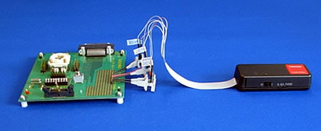
FLASH Programming tool (On-Board Programming type)
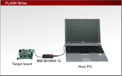
This is small, inexpensive on-board type programming tool corresponding to TOSHIBA's FLASH microcomputers. This is capable of writing/erasing/verifying a program in the built-in FLASH memory.
FLASH Writer
Specifications
| Writing Mode |
On-board/serial |
|---|---|
| Host interface |
USB2.0 |
| Power Supply |
Supplied from the USB bus power. (Note) Capable of supplying the power from the writer body to a target board. (Up to 200 mA, 3.3 V/5.0 V selectable) |
| Dimensions | Approx. 28.5 mm x 77.0 mm x 18.5 mm |
| Weight | Approx. 30g |
Target Devices
For the support information of each device, see "General Catalog (Microcomputers)"
Usage
Available for development/mass-production.
Features
- Available for on-board programming.
- USB connection to a host PC.
- Switchable supply voltage (3.3 V/5 V/Target).
- Available for running with the USB bus power.
- Available for supplying the power to a target board.
- Small and inexpensive.
Contents of Product Package
- FLASH writer
- Communication cable
- Software User Registration and Download Service
Required Items
- Host system
- USB cable (FLASH writer side: B-shaped connector)
- Target connector (Communication connector)
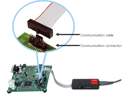
About Connection to the Target System
Seeing the following pin assignment table, etc., lay out/mount the Communication Connector (FTSH series 20pin connector made by Samtec, Inc.) on to the target system where the FLASH Writer(BM1401W0A-G) is to be connected.
The communication cable connector is not included in the product. The customer is kindly requested to prepare it.
FTSH-110-01-[*]-[*][*]-[*][*]
[*] of the part number indicates a connector option. When purchasing, choose a suitable option according to its usage. For details specifications, please visit Samtec, Inc. website.
Communication Connector
| Part Nnumber | Note |
|---|---|
| FTSH-110-01-L-DV-K | Surface mount type with keying shroud (Recommended) |
Communication Connector Pin Assignment Table
| Connector Pin No. | Signal Name |
|---|---|
| 1 | GND(VSS) |
| 3 | MODE |
| 5 | GND(VSS) |
| 7 | VDD |
| 9 | GND(VSS) |
| 11 | /RESET |
| 13 | GND(VSS) |
| 15 | TxD(OCDCK) |
| 17 | GND(VSS) |
| 19 | RxD(OCDIO) |
| Connector Pin No. | Signal Name |
|---|---|
| 2 | OPEN |
| 4 | GND(VSS) |
| 6 | GND(VSS) |
| 8 | VDD |
| 10 | GND(VSS) |
| 12 | GND(VSS) |
| 14 | GND(VSS) |
| 16 | GND(VSS) |
| 18 | GND(VSS) |
| 20 | GND(VSS) |
(Notes) For the MCU pin numbers, signal names and connection method, be sure to see a data sheet for the target MCU.
(Notes) Minimize on-board wiring between the Communication Connector and MCU. (Shortest wiring recommended)
(Notes) If a control circuit or other parts have been connected to the signals (TxD, RxD, RESET) on the target system, which are to be connected to FLASH Writer, disconnect them with jumpers because they may affect operation of FLASH Writer.
Connect Pins 15 and 19 to the TxD and RxD pins of the microcomputer, respectively.
(Notes) For "MODE" signal of Pin 3, connect the MODE pin of this product to the TEST6 pin of the TMP77FM70, when writing to the TLCS-770 series (TMP77FM70).
(Notes) Configure a circuit so that a device's power pin (VDD) will rise to the VDD level faster than the other control pins.
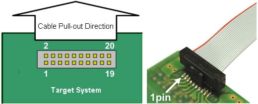
Note for Layout of Communication Cable Connector
The following figure shows the cable pull-out direction and connector pin position, when the FLASH Writer is connected. To design the board, take into account interference with other parts at the time of connecting the communication cable. For a connector size, please visit Samtec, Inc. website.
About the Operating Voltage/Clock Frequency
- To write with the power supply on the target system, it is necessary to provide a supply voltage for the target system within a FLASH Memory write/erase operation assurance range. An out-of-range supply voltage cannot assure operation. For the FLASH Memory write/erase operation assurance range, see the data sheet for the microcomputer.
- Available baud rates are generated by the microcomputer's reference clock. Some of them are not available depending on the clock frequency. For the clock frequency and available baud rates, see the data sheet for the microcomputer.
Precautions for USB Connection
- Connect FLASH Writer to the host system with USB. (USB2.0, full-speed)
- To newly connect FLASH Writer to the host system, it is necessary to install a USB driver.
FLASH Programmer
FLASH Programmer is software running on the host PC.
The FLASH Programmer keeps adding adaptable devices and improving operability.
Specifications
| Applicable MCU | FLASH microcomputers of the series below TLCS-870/C1 Series TLCS-870/C Series TLCS-870/X Series TLCS-900/L1 Series TLCS-900/H1 Series TLCS-900/H Series TX19A Series |
|---|---|
| Applicable OS | Windows® 10 |
| Device functions |
Save, program, read, erase, blank check, verify, compare, auto programming |
(Note-1) Microsoft® and Windows® are the registered trademarks or trademarks of U.S. Microsoft Corporation in the United States, Japan and other countries.
Accessory
Communication Cable
The communication cable is used to connect the emulator or the FLASH Writer to the target system. It is pre-plugged to the emulator or the FLASH Writer.
The communication cable is available from Samtec, Inc. For detailed specifications, please visit Samtec, Inc. website.
The recommended product can also be purchased from the following agencies.
| Name | Part Number | Remark |
|---|---|---|
| Communication cable |
FFSD-10-D-07.00-01-N |
Pre-plugged to the emulator or the FLASH Writer |
Communication Connector
The communication connector is used to connect the FLASH Writer to the target system. The part numbers shown below are examples. Other mount types, such as through-hole, and other mating options are also available to meet the specific needs of each customer.
The communication connector is available from Samtec, Inc. For detailed specifications, please visit Samtec, Inc. website.
The recommended product can also be purchased from the following agencies.
| Name | Part Number | Remark |
|---|---|---|
| Communication connector | FTSH-110-01-L-DV-K | Surface mount type with keying shroud (Recommended) |
Option Tools/Option Parts
Various option tools and option parts are available from third parties for efficient project development. Find products that meet your specific application needs. For the specifications and order information on these products, please contact each third party directly.
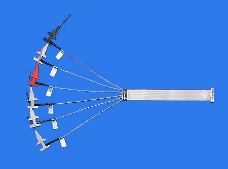
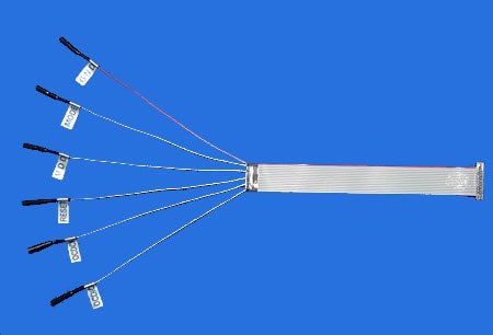
Test Clip Communication Cable
| Communication Cable | FLASH MCU (Note-1) |
|---|---|
| GND | VSS |
| MODE | (Note-2) |
| VDD | VDD |
| RESET | /RESET |
| OCDCK | TxD |
| OCDIO | RxD |
(Note-1) For the pin numbers of the serial transmit (TxD), serial receive (RxD), VDD, VSS, and /RESET pins, refer to the datasheet of the FLASH MCU.
(Note-2) When programming the on-chip FLASH memory of the TMP77FM70 of the TLCS-770 Series, connect the MODE pin of the BM1401W0A-G to the TEST6 pin of the TMP77FM70.
The test clip communication cable is a connecting cable that connects to a target system with test clips. This cable enables the FLASH Writer to be connected to a target system without mounting a dedicated connector on the target system.
The test clip communication cable is available from ADLINKS Corporation. For product specifications, please visit ADLINKS Corporation website.
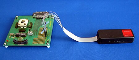
Socket Type Communication Cable
| Communication Cable | FLASH MCU (Note-1) |
|---|---|
| GND | VSS |
| MODE | (Note-2) |
| VDD | VDD |
| RESET | /RESET |
| OCDCK | TxD |
| OCDIO | RxD |
(Note-1) For the pin numbers of the serial transmit (TxD), serial receive (RxD), VDD, VSS, and /RESET pins, refer to the datasheet of the FLASH MCU.
(Note-2) When programming the on-chip FLASH memory of the TMP77FM70 of the TLCS-770 Series, connect the MODE pin of the BM1401W0A-G to the TEST6 pin of the TMP77FM70.
The socket type communication cable is a connecting cable that connects to a target system with sockets. This cable enables the FLASH Writer to be connected to a target system without mounting a dedicated connector on the target system.
The socket type communication cable is available from ADLINKS Corporation. For product specifications, please visit ADLINKS Corporation website.
Adapter for writing to OTP
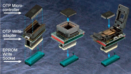
This is an adapter for converting the OTP microcontroller pin-out to a standard EPROM pin configuration. This OTP write-adapter allows the use of an off-the-shelf EPROM writer to program/verify an OTP microcontroller. Adapters are available for any OTP microcontroller.