IH Cooking Heater

IH Cooking Heater

Such as high breakdown voltage, low power consumption and miniaturization are important in designing IH cooking heater. Toshiba provides information on a wide range of semiconductor products suitable for IH coil driving units, motor driving units, current detecting unit, etc., along with circuit configuration examples.

Overall block diagram

Click the area you want to check the details in the overall block diagram. Show links to our proposed sub-block diagram.

 Temp. Sensor Temp. Sensor AC-DC AC-DC DC-DC DC-DC Regulator Regulator Fan, Gate Driver Fan, Gate Driver MCU, Amplifier, Display, LED, etc. MCU, Amplifier, Display, LED, etc. +24 V / 0.5 A +24 V / 0.5 A +5 V / 1.0 A +5 V / 1.0 A Fan Fan 7seg LED 7seg LED Status LEDs Status LEDs Buzzer Buzzer MCU MCU Control Buttons Control Buttons 200 V AC 200 V AC 200 V AC 200 V AC IH Coil IH Coil Current Sensor Current Sensor LED Driver LED Driver MOSFET MOSFET IGBT IGBT IGBT IGBT Gate Driver GateDriver Gate Driver GateDriver Segment LCD Segment LCD LED drive circuit Motor drive circuit IH coil drive circuit/Current detector Display and operation section
IH coil drive circuit/Current detector

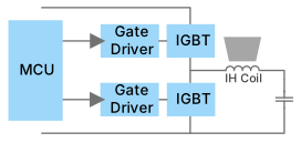
Example of IH current resonance circuit for driving IGBT with a gate driver coupler

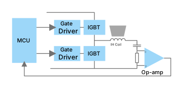
Example of current detection circuit for IH coil using shunt resistor and operational amplifier

Brushless DC motor drive circuit

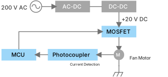
Example of motor drive circuit using a photocoupler for motor current feedback

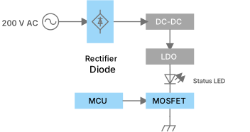
LED drive circuit

Example of LED drive circuit using a MOSFET as a low-side switch

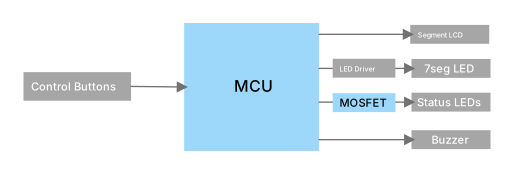
Display and operation section

Example of display control section

Sub block diagram

IH coil drive circuit/Current detector
IH coil drive circuit (Current resonance circuit)

Example of IH current resonance circuit for driving IGBT with a gate driver coupler

Example of IH current resonance circuit for driving IGBT with a gate driver coupler
Rail to Rail output enables the system to operate stably and reduce conduction losses.
Part Number
Toshiba Package Name SO6L SO6L SO6L SO6L SO6L SO6L
BVS (Min) [Vrms] @ t = 60 [s] 5000 5000 5000 5000 5000 5000
VCC / VDD (Min) [V] 10 10 10 15 15 15
VCC / VDD (Max) [V] 30 30 30 30 30 30
ICC / IDD (Max) [mA] 3 3 3 3 3 3
Output Interface totem-pole(BUF) totem-pole(BUF) totem-pole(BUF) totem-pole(BUF) totem-pole(BUF) totem-pole(BUF)
The various built-in protective functions make it easy to design the gate drive circuit.
Part Number
Toshiba Package Name SO16L
BVS (Min) [Vrms] @ t = 60 [s] 5000
VCC / VDD (Min) [V] 15.0
VCC / VDD (Max) [V] 23.5
ICC / IDD (Max) [mA] 10.2
Output Interface totem-pole(BUF)
High speed switching and low saturation voltage characteristics contribute to high efficiency of the set.
Part Number
Toshiba Package Name TO-3P(N) TO-3P(N) TO-3P(N) TO-247 TO-247
VCES (Max) [V] 600 650 1100 1350 1350
IC (Max) [A] 59 60 60 40 30
AD converters, timers, and Pulse Width Modulation output circuits are built in. The system-control runs at low power.
Current detector

Example of current detection circuit for IH coil using shunt resistor and operational amplifier

Example of current detection circuit for IH coil using shunt resistor and operational amplifier
Rail to Rail output enables the system to operate stably and reduce conduction losses.
Part Number
Toshiba Package Name SO6L SO6L SO6L SO6L SO6L SO6L
BVS (Min) [Vrms] @ t = 60 [s] 5000 5000 5000 5000 5000 5000
VCC / VDD (Min) [V] 10 10 10 15 15 15
VCC / VDD (Max) [V] 30 30 30 30 30 30
ICC / IDD (Max) [mA] 3 3 3 3 3 3
Output Interface totem-pole(BUF) totem-pole(BUF) totem-pole(BUF) totem-pole(BUF) totem-pole(BUF) totem-pole(BUF)
The various built-in protective functions make it easy to design the gate drive circuit.
Part Number
Toshiba Package Name SO16L
BVS (Min) [Vrms] @ t = 60 [s] 5000
VCC / VDD (Min) [V] 15.0
VCC / VDD (Max) [V] 23.5
ICC / IDD (Max) [mA] 10.2
Output Interface totem-pole(BUF)
High speed switching and low saturation voltage characteristics contribute to high efficiency of the set.
Part Number
Toshiba Package Name TO-3P(N) TO-3P(N) TO-3P(N) TO-247 TO-247
VCES (Max) [V] 600 650 1100 1350 1350
IC (Max) [A] 59 60 60 40 30
An isolation amplifier suitable for current and voltage detection of motors and inverters.
Part Number
Toshiba Package Name SO8L(LF4)
Output Interface Analog output
BVS (Min) [Vrms] @ t = 60 [s] 5000
VDD1 (Max) [V] 5.5
VDD2 (Max) [V] 5.5
IDD1 (Max) [mA] @ VIN+ = 0 [V] 12
IDD2 (Max) [mA] @ VIN+ = 0 [V] 10
AD converters, timers, and Pulse Width Modulation output circuits are built in. The system-control runs at low power.
Brushless DC motor drive circuit

Example of motor drive circuit using a photocoupler for motor current feedback

Example of motor drive circuit using a photocoupler for motor current feedback
High CTR (Current Transfer Ratio) is realized even in low input current range (IF = 0.5 mA).
Part Number
Toshiba Package Name 4pin SO6 4pin SO6
BVS (Min) [Vrms] @ t = 60 [s] 3750 3750
VCEO (Max) [V] 80 80
Topr [°C] -55 to 125 -55 to 110
U-MOS series MOSFETs contribute to energy saving and miniaturization by improving the trade-off characteristics between on-resistance and capacitance.
Part Number
Toshiba Package Name SOT-723 (VESM) SOT-563 (ES6)
VDSS (Max) [V] 20 20
ID (Max) [A] 0.8 0.8
RDS(ON) (Max) [Ω] @ |VGS| = 4.5 [V] 0.235 0.235
Polarity N-ch N-ch×2
AD converters, timers, and Pulse Width Modulation output circuits are built in. The system-control runs at low power.
LED drive circuit
LED drive circuit

Example of LED drive circuit using a MOSFET as a low-side switch

Example of LED drive circuit using a MOSFET as a low-side switch
U-MOS series MOSFETs contribute to energy saving and miniaturization by improving the trade-off characteristics between on-resistance and capacitance.
Part Number
Toshiba Package Name SOT-723 (VESM) SOT-563 (ES6)
VDSS (Max) [V] 20 20
ID (Max) [A] 0.8 0.8
RDS(ON) (Max) [Ω] @ |VGS| = 4.5 [V] 0.235 0.235
Polarity N-ch N-ch×2
Wide range of products are provided, mainly small surface mount package that is suitable for high density assembly.
Part Number
Toshiba Package Name M-FLAT
VRRM (Max) [V] 600
IF(AV) (Max) [A] 1
AD converters, timers, and Pulse Width Modulation output circuits are built in. The system-control runs at low power.
Display and operation section

Example of display control section

Example of display control section
U-MOS series MOSFETs contribute to energy saving and miniaturization by improving the trade-off characteristics between on-resistance and capacitance.
Part Number
Toshiba Package Name SOT-723 (VESM) SOT-563 (ES6)
VDSS (Max) [V] 20 20
ID (Max) [A] 0.8 0.8
RDS(ON) (Max) [Ω] @ |VGS| = 4.5 [V] 0.235 0.235
Polarity N-ch N-ch×2
AD converters, timers, and Pulse Width Modulation output circuits are built in. The system-control runs at low power.

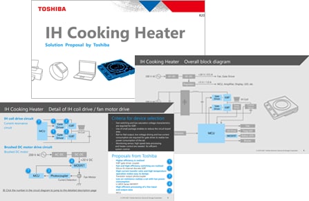
Solution Proposal

These documents explain the key points of recommended semiconductor products and their features. Please use them for product selection.

Reference Design

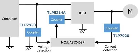
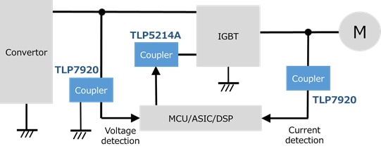
Application block diagram of application circuit (current sensing) of the TLP7920 isolation amplifier.
Application Circuit (Current sensing) of the TLP7920 Isolation Amplifier
This reference design provides design guide and example of simulation waveform for phase current detection with optical isolation amplifier for motor control of servo and inverter.
Application block diagram of application circuit (voltage sensing) of the TLP7920 isolation amplifier.
Application Circuit (Voltage sensing) of the TLP7920 Isolation Amplifier
This reference design provides design guide and example of simulation waveform for bus voltage detection with optical isolation amplifier for motor control of servo and inverter.
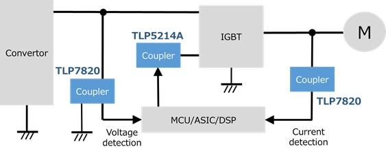
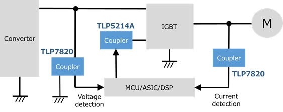
Application block diagram of aplication circuit (current sensing) of the TLP7820 isolation amplifier.
Application Circuit (Current sensing) of the TLP7820 Isolation Amplifier
This reference design provides design guide and example of simulation waveform for phase current detection with optical isolation amplifier for motor control of servo and inverter.
Application block diagram of application circuit (voltage sensing) of the TLP7820 isolation amplifier.
Application Circuit (Voltage sensing) of the TLP7820 Isolation Amplifier
This reference design provides design guide and example of simulation waveform for bus voltage detection with optical isolation amplifier for motor control of servo and inverter.

Documents

Video

Design & Development

Switched Mode Power Supply Library

you can select and download various basic topologies of a power supply unit based on your actual requirements in order to verify the behavior of MOSFETs with your simulation environment.

Motor Control and Driver Circuit Library

you can select and download various basic topologies of motor driver such as three-phase inverter circuit based on your actual requirements in order to verify the behavior of MOSFETs and another devices for your simulation environment.

Online Simulator

This service allows users to easily perform pre-verification of MOSFETs without the need to build a simulation environment.

EDA/CAD Model Library

We provide simulation data, 3D models of packages, and land pattern models (2D models) used when developing product boards.

MCU Motor Studio

MCU Motor Studio features a PC Tool and motor control firmware dedicated to the TXZ+TM Family Advanced Class microcontrollers from Toshiba.

Contacts

Technical inquiry

Contact us

Contact us

Frequently Asked Questions

FAQs
  • Arm and Cortex are registered trademarks of Arm Limited (or its subsidiaries) in the US and/or elsewhere.
  • M-FLATTM, TXZ+TM are trademarks of Toshiba Electronic Devices & Storage Corporation.
  • Other company names, product names, and service names may be trademarks of their respective companies.
Membership registration required
A new window will open