


Implementing Efficient and Accurate Servo Drives in Robots, SCARA and Autonomous Guided Vehicles.
Introduction
Man’s fascination with building machines that do work for the human race goes back a long way. The first recorded idea of a ‘metal man’ is probably Talos[1], a giant bronze man created by the Greek god Hephaestus and gifted to either Minos or Europa to protect the island of Crete. The word robot was coined by Karel Čapek[2] in the 1920s, meaning “serf labour” or, figuratively speaking, “drudgery” in his native Czech, leading to its use in a wide range of science fiction writing. Since then, robots continue to fascinate the mind, appearing both in villainous roles, such as the cyborg assassin in Terminator, or as mechanoid heroes, such as the diligent sentient garbage collector WALL-E. Major advances in industrial robots came about in the 1970s, with KUKA[3] delivering an arm with six electromechanically driven axes known as FAMULUS. Since then, it is impossible to imagine a world without robots, with them being used to build and paint cars, lift huge work pieces in factories, explore Mars, and even participate in surgical procedures.
Today’s robots mostly remain fenced off, protecting the human workforce from these immensely powerful machines. This is because they typically only execute predefined motion, unaware of the environment within which they operate. However, robotic devices are increasingly interacting more closely with humans, taking on new forms and roles as the costs associated with their design and electronics drop. As a result, collaborative robots, or cobots, could conceivably operate alongside humans, much like humans do, on a linear manufacturing process. Smaller, so-called limited compliance, robots, known as Selective Compliance Articulated Robot Arms (SCARA), move in the X-Y axis but remain rigid in the Z-axis. This makes for a simpler, more cost-effective machine suitable for moving objects in a limited way, such a picking and placing items into trays on a manufacturing line, or changing tools and dispensers on other machines. Autonomous Guided Vehicles also being to this grouping of machines and are already being trialled in our cities, delivering food and groceries, and performing an essential role in semiconductor manufacturing and logistics centres. Even lawnmowers have become robotic, leaving their charging garages on a daily basis to keep our luscious lawns under control.
Chapter 1: Robotics implementation triangle
At the core of any robot or Autonomous Guided Vehicle implementation there are three core elements surrounding the control of the motors used to implement the servos: the controller, the power delivery, and the feedback loop. The controller element is responsible for ensuring commands from the motion controller are sent to the motor. Today’s motors are typically either stepper types or brushless DC (BLDC), so the motor control algorithm needs to be implemented too, ideally in a manner that offers the utmost electrical efficiency. This is directly coupled with the power delivery system that needs to be realised with efficient switching technology. This ensures that as much power as possible is passed into the motor’s coils, and as little as possible is lost as waste heat. If achieved, it contributes significantly to minimising the volume of the final solution, preferably without forced cooling, allowing it to be integrated into a robot arm or SCARA rather having it in an external control box.
The accuracy of the control of individual axes in a robot’s arms, or wheel rotation in Autonomous Guided Vehicle s, depends on the system’s ability to track the precise position of the motor’s rotor. A wide range of approaches are available, such as encoders and resolvers, but consideration needs to be made for the size and weight of the solution balanced against its accuracy and cost. The output of the positioning system will also likely need some sort of signal conditioning to convert the signals to a level that the controller can use.
With such a varied range of elements and circuitry needed, a broad scope of engineering competency is required to bring together a system that fulfils the design goals defined. Thanks to the increased interest in robotic technology and Autonomous Guided Vehicle s, coupled with the lower costs associated with them, there are many start-ups tackling various niche markets while other established companies are branching out to augment their existing offerings.
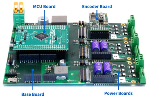
To simplify the efforts of engineering teams starting along this road, Toshiba has developed a highly flexible and configurable Servo Drive Reference Model (RM) that combines all the elements needed (figure 1). Consisting of a main board that links all the pieces together, the modular approach allows the controller, power stage, and encoder or resolver used to be swapped in and out, allowing rapid evaluation of the pros and cons of different approaches.
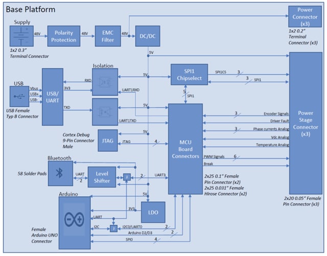
The base board is kept as simple as possible, providing several sets of connectors to support the modular configuration approach (figure 2). The first provides a plug-in area for the MCU board selected, next to an Arduino-compatible layout allowing standard shields to be integrated. This allows for CAN, Ethernet, other networking technologies, or other circuits to be easily integrated for assessment. A footprint is also available for the PAN1762 Bluetooth® module that is based upon Toshiba technology. Three connectors along one of the long sides provides room to attach up to three of the Low-Voltage Power Boards along with their optional Encoder Boards. Connectivity is provided via a USB-to-UART converter that is isolated from the MCU, while the remainder of the design provides polarity protection, power, and level shifting where needed.
Chapter 2: Accurate control with dedicated controllers
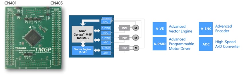
At the heart of the system is an interchangeable MCU board (figure 3). The MCU included, the 100-pin M4K, features an Arm® Cortex® M4F operating at 160 MHz. Featuring 256 kB flash memory, 32 kB of data flash, 24 kB of SRAM, and a floating-point unit, it is ideally dimensioned for a range of motor control approaches. In addition, it features a collection of peripherals that are optimised for motor control.
In total, three peripherals are tightly integrated with one-another to optimise and simplify motor control: an Advanced Vector Engine Plus (A-VE+) module, a 12-bit analogue-to-digital (ADC) converter, and an Advanced Programmable Motor Control (A-PMD) timer block. The A-VE+ block can support Field-Oriented Control (FOC) of a single motor, although the ADC and A-PMD can support a further two motors together with an FOC algorithm operating in software.
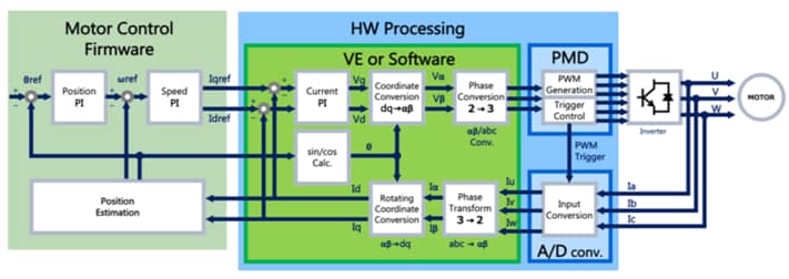
The A-VE+ implements the complex mathematical functions required for FOC that would typically demand the use of a digital signal processor. FOC uses a sinusoidal variable frequency commutation method that keeps both rotor and stator magnetic fields at 90° under all operating conditions, thus ensuring maximum torque and electrical efficiency. To achieve this, the precise position of the rotor is needed. With their high torque load, robots and SCARA solutions will need to mount an encoder or resolver onto the rotor to provide this positional feedback. This information is fed into the A-VE+ module directly into the positional PI regulator (figure 4). This information is then evaluated to determine the deviation between the desired and actual rotor speed, along with any change in speed requested from the system, within the control loop. The PI is also implemented in the A-VE+ hardware. This stage delivers the next desired electrical commutation point that is converted from a 2-phase representation to 3-phase using an inverse Park Clarke transform. This final calculation result can then be passed to the timer block of the MCU, the A-PMD, to set the pulse-width modulated (PWM) outputs appropriately for the next phase of commutation.
The advantage of the A-VE+ module over pure software alternatives is the determinism that results. Software algorithms will require varying amounts of processing time to execute the mathematics algorithms, determined by the complexities of the libraries being called and the values being evaluated. In real-time systems this can result in jitter in responding to other high priority tasks or interrupts. The A-VE+ implementation requires the same amount of time to perform its calculations, regardless of the values being evaluated. Further issues result toward the end of embedded software projects as the compiler’s optimiser is enabled to squeeze further performance improvements out of the system. With the A-VE+ being primarily a hardware implementation, the use of compiler optimisations has a very limited impact on execution time for the FOC implementation and, therefore, results in little deviation in determinism. Thankfully the A-VE+ is also tightly coupled with both the ADC and the A-PMD blocks, allowing the motor control to execute almost autonomously once configured.
Depending on the needs of the system, the designer will choose between an encoder or resolver for determining the rotor position. Resolvers are typically the more expensive option, providing an absolute position in the form of an analogue sine and cosine signal. These can be interfaced with the ADC module of the MCU. Solutions such as Hiperface[4] also require, in addition to their differential sine/cosine channels, an EIA-485 interface for digital communication. This enables the acquisition of absolute positional data, other parameters, and configuration. The MCU can handle this protocol using its integrated UART together with a suitable transceiver, something that is planned to be supported with future encode boards. The positional information can be determined using the 12-bit ADC that offers a conversion time of 1 µs or an external converter solution.
An alternative absolute encoder approach uses a Hall sensor for rotation position but delivers the angular position over a digital Synchronous Serial Interface (SSI). This makes use of a differential clock and data signalling, similar to SPI, but using RS-422 signalling for the physical interface. Other absolute encoders make use of a binary pattern encoded into a disc that is read using an LED and sensor system.
The cheapest solutions are incremental encoders. These only provide rotational information through a phase-offset pair of signals, also known as a quadrature output, together with an index pulse that occurs latest once per mechanical revolution. The Advanced Encoder Input Circuit (A-ENC32) module within the MCU is designed to interface to such devices, simplifying the interfacing and decoding and including a noise canceller, something useful in the electrically noisy environment of motor control. Such encoders can also be interfaced with general purpose I/Os or an input capture hardware block, such as that integrated into the M4K’s 32-bit Timer Event Counter (T32A).
Reference link:
Chapter 3: Power at the right time, in the right place
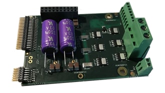
Providing the power delivery to the motor selected is the Low-Voltage Power Board. This accepts an input voltage of up to 48 V and integrates a 3-phase inverter based upon TPW3R70APL 100 V MOSFETs (figure 5). This makes the board suitable for power dissipation of up to 10 W and a heatsink can be fitted if required. The MOSFET is based upon the U-MOS IX-H generation of process technologies that offers improved trade-off between low on resistance and Qg, QSW and QOSS. This particular MOSFET offers a low drain-source resistance of 3.1 mΩ (VGS = 10 V) and QOSS of just 74 nC (typical). Its absolute rated power dissipation is 170 W (25 °C) while offering a channel-to-case thermal resistance (bottom-drain side thermal resistance between channel and case) Rth(ch-c) of just 0.88 °C/W. This MOSFET is part of a wider line-up of devices supporting voltages from 20 V to 250 V in both SMD and THD packages, some of which, such as DSOP, provide top-side cooling pads.
This makes the board suitable for BLDC motors in the 20 W to 200 W class. Current measurement is implemented in the low side, with a TC75W58FU comparator selected to provide a fault feedback signal to the base board. Further protection is implemented thanks to a temperature sensor. The phase currents for the motor are also linked back to the base board for use by the MCU, where required. The board features two further connecters. One is used for controlling a brake, connected to a GPIO pin through a SSM3K16 MOSFET and a TLP3122 photorelay. The other allows the connection of an encoder board, if required.
Reference links:

Chapter 4: Feedback of rotor position
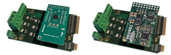
The final link in the loop is the feedback of the rotor position. Since this can take many forms, provision is made for a selection of modular boards that can be attached to each Low Voltage Power Board. Currently two boards are available: one for differential encoders and another for resolvers (figure 6).
The Differential Encoder Board accepts up to three differential Hall sensor signals, converting to a single-ended A, B and Z signal. An SPI interface provides communication for setting parameters, such as input thresholds and receiver functionality, and reading out the status of the encoder.
The Resolver Encoder Board functions in more or less the same manner, with A, B, and Z signals plus SPI for configuration and status, but evaluates the sine/cosine resolver output that is additionally passed through a low-pass filter to improve measurement accuracy in the electrically noisy motor control environment.
Chapter 5: System Demonstration Platform
The Servo Drive RM is supported with firmware for the MCU based upon a real-time operating system. This is coupled with example code that provides an application programming interface (API) that simplifies the control and configuration of each motor drive circuit. This ranges from StartMotor and StopMotor commands, to requests for motor state or controlling of speed and torque factor.
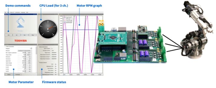
To demonstrate the capability of the platform, an AR3[5] robot arm has been modified to use BLDC motors and Hall sensor-based encoders together with the firmware described and a graphical user interface (GUI). The GUI provides an overview of the status of the firmware along with the parameter settings for each motor axis. Feedback for the load on the CPU is also displayed in real time, together with a graph of the motor RPM (figure 7). The robot arm is fitted with 24 V BLDC motors and gearboxes of 1:50 or 1:64 ratios, delivering a positioning accuracy of 0.2° to 0.3° depending on the axis. Acceleration of up to 300 rad/s2 are possible.
Summary
While robots have been around for many decades, it is only now that they are attaining a price-point that allows them to become more ubiquitous. Robot arms, in the form of cobots, are likely to work alongside us in factories or even the operating theatre in a surgical environment, while SACRA devices, with their limited axis motion, are well suited to picking and placing of objects. Even in the home, in the form of robotic lawnmowers, or on our streets as Autonomous Guided Vehicle s delivering food and groceries, the market for robotic solutions is moving at pace. High efficiency is required, regardless of mains or battery power, along with enough accuracy for the task to be executed. Getting the motor drive correct for each axis or element of the robotic system is essential in order that the higher-level motion control delivers the solution customer’s need. The Servo Drive RM provides a modular approach to explore all these aspects of the design of the drive system and already shows what is possible in the robotic arm demonstrator. Drawing together optimised technologies from the Toshiba portfolio, from a MCU tuned for BLDC motor control, to power devices delivering low on resistance, designers are well supported throughout the exploratory and development processes.
References
Download PDF
Please click the button to download the PDF file.
Related Links

The Journey of Motor Control
More about Toshiba Electronic Devices & Storage Corporation's motor solutions.
* The Bluetooth® word mark is a registered trademark owned by Bluetooth SIG, Inc.
* Arm and Cortex are registered trademarks of Arm Limited (or its subsidiaries) in the US and/or elsewhere.
* TXZ+™ is a trademark of Toshiba Electronic Devices & Storage Corporation.
* Other company names, product names, and service names may be trademarks of their respective companies.