
- General Top
- SEMICONDUCTOR
- STORAGE
- COMPANY
-
My ToshibaSemicon
- Semiconductor Top
-
ApplicationsAutomotive
Body Electronics
xEV
In-Vehicle Infotainment
Advanced Driver-Assistance Systems (ADAS)
Chassis
IndustrialInfrastructure
BEMS/HEMS
Factory Automation
Commercial Equipment
Consumer/PersonalIoT Equipment
Healthcare
Wearable Device
Mobile
Computer Peripherals
-
ProductsAutomotive Devices
Discrete Semiconductor
Diodes
Transistors
Logic ICs
Analog Devices
- Automotive SmartMCD™ (Integreted SoC Conbining Microcontroller and Driver)
- Automotive Brushless Motor Driver ICs
- Automotive Brushed DC Motor Driver ICs
- Automotive Stepping Motor Driver ICs
- Automotive Driver ICs
- Automotive System Power Supplies ICs
- Automotive audio power amplifier ICs
- Automotive Network Communication
Digital Devices
Wireless Devices
※
 : Products list (parametric search)Power Semiconductors
SiC Power Devices
※
: Products list (parametric search)Isolators/Solid State RelaysPhotocouplers
Digital Isolators
Solid State Relays
Fiber Optic Transmitting Modules
※
: Products list (parametric search)MOSFETsIGBTs/IEGTsBipolar Transistors※
: Products list (parametric search)Diodes※
: Products list (parametric search)MicrocontrollersMotor Driver ICsIntelligent Power ICs※
: Products list (parametric search)Power Management ICsLinear ICs※
: Products list (parametric search)General Purpose Logic ICsLinear Image SensorsOther Product ICsOther Product ICs
※
: Products list (parametric search) -
Design & Development
Design & Development
Innovation Centre
At the Toshiba Innovation Centre we constantly strive to inspire you with our technologies and solutions. Discover how to place us at the heart of your innovations.
-
Knowledge
Knowledge
Highlighted Topics
Further Materials
Other
- Where To Buy


- Part Number & Keyword Search
- Cross Reference Search
- Parametric Search
- Stock Check & Purchase
This webpage doesn't work with Internet Explorer. Please use the latest version of Google Chrome, Microsoft Edge, Mozilla Firefox or Safari.
require 3 characters or more. Search for multiple part numbers fromhere.
The information presented in this cross reference is based on TOSHIBA's selection criteria and should be treated as a suggestion only. Please carefully review the latest versions of all relevant information on the TOSHIBA products, including without limitation data sheets and validate all operating parameters of the TOSHIBA products to ensure that the suggested TOSHIBA products are truly compatible with your design and application.Please note that this cross reference is based on TOSHIBA's estimate of compatibility with other manufacturers' products, based on other manufacturers' published data, at the time the data was collected.TOSHIBA is not responsible for any incorrect or incomplete information. Information is subject to change at any time without notice.
require 3 characters or more.
TLCS-900/H1 Series Development System
In-Circuit Emulation System
The RTE900/H1 In-Circuit Emulation System consists of Integrated Development Environment, RTE900/H1 In-Circuit Emulator and Probe set.
| Host interface | USB2.0 High-speed | |
|---|---|---|
| Emulation memory | 4 Mbytes | |
| Event | Number of points | 8 points |
| Comparison items | Address, data, status, external input | |
| Comparison conditionscondition | Match, unmatch, range | |
| Pass count | 1 to 256 times | |
| Event trigger actions | Break, trace control, timer control, external trigger output | |
| Event combinations | AND, OR, sequential | |
| Hardware break | 4 points | |
| Software break | 1024 points | |
| Trace memory Capacity | 64 K frames (Notes-1) | |
| Trace memory Modes | Free trace, trigger trace, sampling trace | |
| Trace items | PC address, data address, data value, status, external output, external input, tag timer, event | |
| Trace overflow actions | Overwriting, overwriting prohibit, break | |
| Timer measurement | Run timer: 1 channel Lap timer: 4 channels (max., min., average, count) |
|
| Memory access | Memory display during program execution | 128 bytes |
| Memory rewrite during program execution | 1 address(byte/word/Long word either) (Notes-2) | |
| Program variables | Display | Binary, octal, decimal or hexadecimal display can be selected for each variable. |
| Registration | Variables, arrays, structures and unions can be registered by the elements. | |
| Sauce display | - Source - Source + assembler code - Source + assembler code + machine language |
|
| External output | 1 line | |
| External input | 1 line | |
| Performance analysis: Module time measurement | - | |
| Performance analysis: Coverage measurement | C0 coverage | |
| Flash programming/security feature | - | |
(Notes-1) There are some cases where the trace memory capacity varies by a tracing condition or operating status.
(Notes-2) A break occurs whenever rewritten.
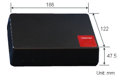
Product Configuration and Appearance of RTE900/H1 In-Circuit Emulator
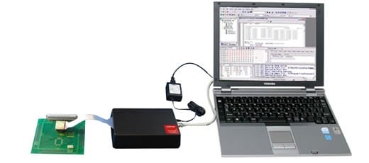
Content of Product
- RTE900/H1 In-Circuit Emulator main body
- AC adapte (Note)
- AC cable (Note)
- One license for downloading the Integrated Development Environment from website.
(Note) Products shipped to countries and regions outside Japan do not come with an AC adapter and an AC cable.
Items to Be Prepared by Customer
- Host system
- USB cable (emulator side: B-type connector)
- Probe set (Note 1)
- AC adapte (Note 2)
- AC cable (Note 2)
(Note 1) A probe set is a product combining a Emulator cable, a Emulator connector and a QFP socket for each supported MCU.
(Note 2) Products shipped to countries and regions outside Japan require an AC adapter and an AC cable to be purchased separately.
About AC adapter and an AC cable
If you are using this product outside Japan, use an AC adapter and an AC cable that are compliant with the safety standards of your country or region.
AC adapter compliance specifications
Output voltage: 9[V]
Output current: 1[A] or larger
The DC plug of the AC adapter should have the following outer dimensions and polarity. Not satisfying these requirements will cause malfunction.
About Emulation Operating Voltage/Frequency
| Emuletor | Voltage/Frequency | Remark |
|---|---|---|
| HW92ES230AG | 6MHz~10MHz@3.0V~3.6V 30kHz~34kHz@3.0V~3.6V |
- |
- The emulation power can be only supplied from an In-Circuit Emulatorinternal power source, and the In-Circuit Emulatorinternal power cannot be supplied to a target system.
- A clock on the target system and an In-Circuit Emulatorinternal clock can be selected as an emulation operation clock.
- To operate with a frequency other than an In-Circuit Emulatorinternal clock frequency, it is necessary to replace the clock. For a replacement method, see the In-Circuit Emulator Instruction Manual.
- When the Emulator is used with an external clock, a “resonator” such as a crystal or ceramic resonator cannot be used. When using an external clock, use an “oscillator” and input a square wave of duty 50% from X1 (or XT1) of the QFP socket. Also, leave X2 (or XT2) open.
Precautions for USB Connection
- The emulator is connected to the host system via the USB. (USB2.0 High-speed)
- To newly connect the emulator to the host system, it is necessary to install a USB driver.
Accessory
Probe Set
A probe set is a product combining a Emulator cable, a Emulator connector and a QFP socket for each supported MCU.
The probe set is manufactured by TOKYO ELETECH CORPORATION. For information about the specification of the probe set, please refer to TOKYO ELETECH CORPORATION's website.
- Move to TOKYO ELETECH CORPORATION website
QFP Socket Cover (Top Cover for IC Package)
The QFP socket cover is used, together with the target connector, to mount an MCU on the target system.
The QFP socket cover is manufactured by TOKYO ELETECH CORPORATION. For information about the specification of this product, please refer to TOKYO ELETECH CORPORATION’s website.
- Move to TOKYO ELETECH CORPORATION website