
- General Top
- SEMICONDUCTOR
- STORAGE
- COMPANY
-
My ToshibaSemicon
- Semiconductor Top
-
ApplicationsAutomotive
Body Electronics
xEV
In-Vehicle Infotainment
Advanced Driver-Assistance Systems (ADAS)
Chassis
IndustrialInfrastructure
BEMS/HEMS
Factory Automation
Commercial Equipment
Consumer/PersonalIoT Equipment
Healthcare
Wearable Device
Mobile
Computer Peripherals
-
ProductsAutomotive Devices
Discrete Semiconductor
Diodes
Transistors
Logic ICs
Analog Devices
- Automotive SmartMCD™ (Integreted SoC Conbining Microcontroller and Driver)
- Automotive Brushless Motor Driver ICs
- Automotive Brushed DC Motor Driver ICs
- Automotive Stepping Motor Driver ICs
- Automotive Driver ICs
- Automotive System Power Supplies ICs
- Automotive audio power amplifier ICs
- Automotive Network Communication
Digital Devices
Wireless Devices
※
 : Products list (parametric search)Power Semiconductors
SiC Power Devices
※
: Products list (parametric search)Isolators/Solid State RelaysPhotocouplers
Digital Isolators
Solid State Relays
Fiber Optic Transmitting Modules
※
: Products list (parametric search)MOSFETsIGBTs/IEGTsBipolar Transistors※
: Products list (parametric search)Diodes※
: Products list (parametric search)MicrocontrollersMotor Driver ICsIntelligent Power ICs※
: Products list (parametric search)Power Management ICsLinear ICs※
: Products list (parametric search)General Purpose Logic ICsLinear Image SensorsOther Product ICsOther Product ICs
※
: Products list (parametric search) -
Design & Development
Design & Development
Innovation Centre
At the Toshiba Innovation Centre we constantly strive to inspire you with our technologies and solutions. Discover how to place us at the heart of your innovations.
-
Knowledge
Knowledge
Highlighted Topics
Further Materials
Other
- Where To Buy


- Part Number & Keyword Search
- Cross Reference Search
- Parametric Search
- Stock Check & Purchase
This webpage doesn't work with Internet Explorer. Please use the latest version of Google Chrome, Microsoft Edge, Mozilla Firefox or Safari.
require 3 characters or more. Search for multiple part numbers fromhere.
The information presented in this cross reference is based on TOSHIBA's selection criteria and should be treated as a suggestion only. Please carefully review the latest versions of all relevant information on the TOSHIBA products, including without limitation data sheets and validate all operating parameters of the TOSHIBA products to ensure that the suggested TOSHIBA products are truly compatible with your design and application.Please note that this cross reference is based on TOSHIBA's estimate of compatibility with other manufacturers' products, based on other manufacturers' published data, at the time the data was collected.TOSHIBA is not responsible for any incorrect or incomplete information. Information is subject to change at any time without notice.
require 3 characters or more.
2.3. Oscillation
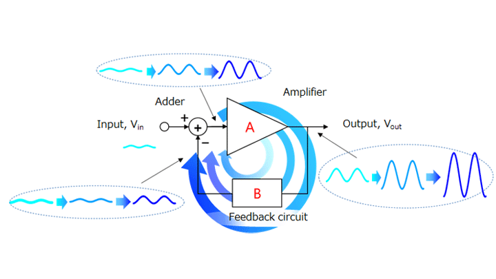
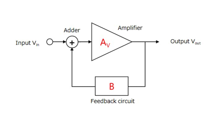
An op-amp is normally used with a feedback circuit as shown in Figure 2-6. There are two types of feedback, positive and negative, as described in Section 2.1. When an op-amp is used as an amplifier, it is configured for negative feedback. Care is required as to the oscillation of a feedback circuit.
A signal or noise that acts as a source of oscillation can develop into oscillation under certain conditions. Here is a brief explanation about oscillation.
A source of oscillation applied to the input passes through the amplifier and the feedback circuit. Then, the adder adds it to the Vin input. Therefore, the output of the adder becomes larger than the initial state. As this process is repeated, the source of oscillation grows, causing oscillation. This is the characteristic of positive feedback.
You might think that oscillation is irrelevant as you use negative feedback . Even if it is negative feedback for the signal to be amplified, it might turn into positive feedback in the higher frequency band.
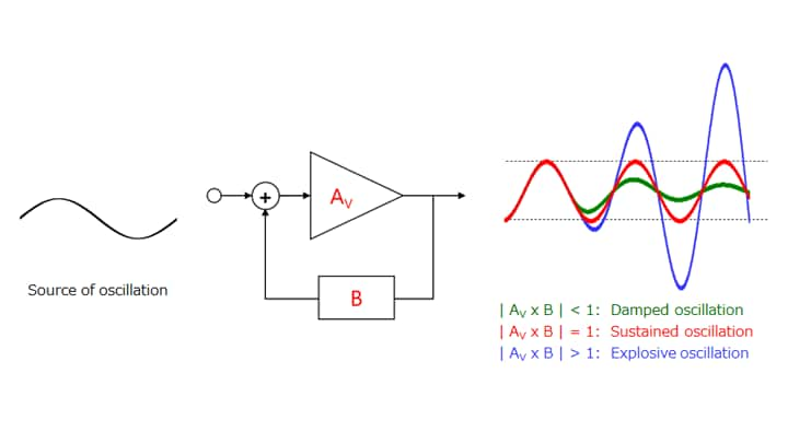
Let the open-loop gain of the op-amp be AV and the feedback factor be B. Then, the transfer function of a feedback circuit is expressed as follows. Both AV and B are complex numbers.
Vout = AV / (1 + AV × B) × Vin
In the case of a negative feedback circuit, AV × B = +|AV × B|. Therefore, Vout provides a stable output as described in Section 2.1. However, the phase of the output lags that of the input at high frequency since all circuits have a delay.
The feedback circuit turns into a positive feedback loop when this phase lag reaches 180 degrees.
The waveform of the output (Vout) differs as shown below, depending on the magnitude of the loop gain (|AV x B|) of positive feedback (i.e., when the signal from the feedback circuit has the same phase as the input signal). When a source of oscillation is applied to the input, a damped, sustained, or explosive oscillation occurs, depending on the magnitude of |AV × B| at the frequency of the oscillation source. Generally, a sustained oscillation is called an oscillation. An explosive oscillation eventually subsides to a sustained oscillation since the open-loop gain (AV) is restricted by the dynamic range of the amplifier.
A sustained oscillation occurs when the loop gain (AV × B) satisfies the following condition (i.e., the denominator of the transfer function becomes zero). This condition is called the Barkhausen condition for oscillation (or simply oscillation condition).
- Amplitude condition: Re (AV × B) = -1
- Phase condition: Im (AV × B) = 0
Note that an explosive oscillation eventually subsides to a sustained oscillation as described above. Therefore, the amplitude condition that causes abnormal oscillation is as follows:
- Amplitude condition: Re (AV × B) < -1
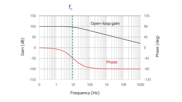
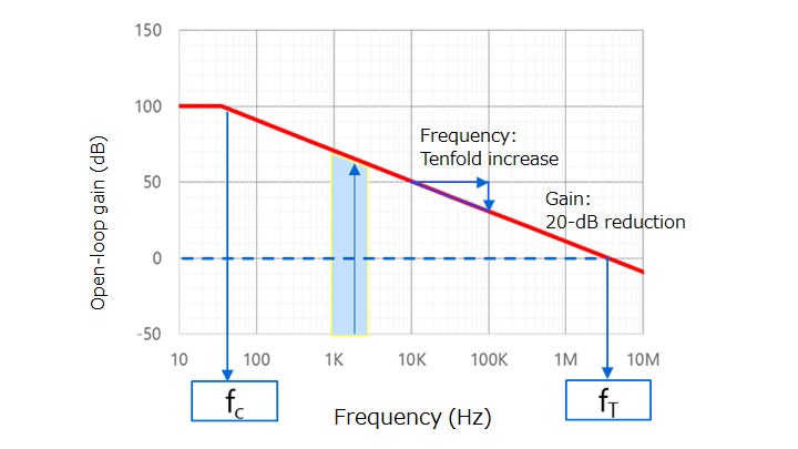
Because of an internal parasitic capacitance, an op-amp has a first-order delay element (as is the case with a first-order lowpass filter) as shown in Figure 2-8.
In the case of typical op-amps, the cut-off frequency of open-loop gain response is between 10 Hz and 100 Hz. The phase of the output lags 45 degrees behind in this frequency range. The phase lag is 90 degrees in the frequency range in which the open-loop gain decreases at a rate of 6 dB per octave.
If the gain-vs-frequency curve has such characteristics with only a main pole, a margin of 90 degrees remains until oscillation occurs. Therefore, oscillation is unlikely to occur.

In reality, an op-amp has multiple poles. The cut-off frequency (fc) shown in Figure 2-9 is called the main pole. The frequency pole at fc2 close to the unity gain cross frequency (fT) is called a second pole. Although there are more poles at higher frequencies, they do not cause any practical problem.
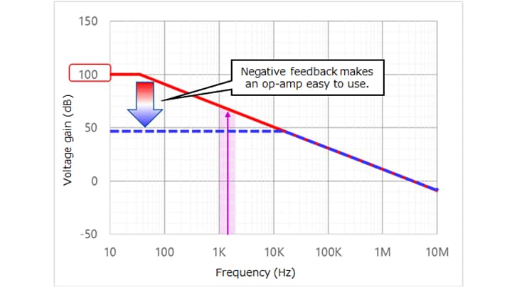
As shown in Figure 2-9, the slope of the open-loop gain curve changes from 6 dB per octave to 12 dB per octave at fc2. The phase lag also increases further by another 45 degrees. This phase lag does not cause any problem when fc2 is higher than the unity gain cross frequency (fT). However, even when fc2 is lower than fT, care should be taken when using op-amps as unity gain amplifiers such as voltage followers. (If the datasheet for an op-amp states that it can be used with unity gain, it has a second pole at a frequency higher than fT.)
In order to avoid abnormal oscillation, an op-amp should be used in the frequency range (fc to fc2) in which the open-loop gain decreases at a rate of 6 dB per octave. Note, however, that, at a frequency close to fc2, an op-amp is affected by a second pole, causing a power loss and a phase delay. To avoid its effects completely, the closed-loop bandwidth (fCL) should be less than one-fifth of fc2.
The above is a discussion on the oscillation of an op-amp itself.
It is also necessary to ensure that external circuitry is also free from oscillation (e.g., phase delay).
For example, this consideration applies to an application in which a capacitive load is driven by an op-amp. Oscillation occurs if the cut-off frequency due to the capacitive load is within the range in which the loop gain is greater than 1. In order to prevent oscillation, it is necessary, for example, to add a resistor in series with a capacitor. Even when an op-amp is not connected with a load, care should be taken as to wire or other capacitance. Minimize the length of the wire from the op-amp output to the subsequent device and that of the feedback loop.
Related information
Chapter2 Using an op-amp

Related information
- Products
- Application Notes
- FAQs
- Parametric Search
- Stock Check & Purchase