
- General Top
- SEMICONDUCTOR
- STORAGE
- COMPANY
-
My ToshibaSemicon
- Semiconductor Top
-
ApplicationsAutomotive
Body Electronics
xEV
In-Vehicle Infotainment
Advanced Driver-Assistance Systems (ADAS)
Chassis
IndustrialInfrastructure
BEMS/HEMS
Factory Automation
Commercial Equipment
Consumer/PersonalIoT Equipment
Healthcare
Wearable Device
Mobile
Computer Peripherals
-
ProductsAutomotive Devices
Discrete Semiconductor
Diodes
Transistors
Logic ICs
Analog Devices
- Automotive SmartMCD™ (Integreted SoC Conbining Microcontroller and Driver)
- Automotive Brushless Motor Driver ICs
- Automotive Brushed DC Motor Driver ICs
- Automotive Stepping Motor Driver ICs
- Automotive Driver ICs
- Automotive System Power Supplies ICs
- Automotive audio power amplifier ICs
- Automotive Network Communication
Digital Devices
Wireless Devices
※
 : Products list (parametric search)Power Semiconductors
SiC Power Devices
※
: Products list (parametric search)Isolators/Solid State RelaysPhotocouplers
Digital Isolators
Solid State Relays
Fiber Optic Transmitting Modules
※
: Products list (parametric search)MOSFETsIGBTs/IEGTsBipolar Transistors※
: Products list (parametric search)Diodes※
: Products list (parametric search)MicrocontrollersMotor Driver ICsIntelligent Power ICs※
: Products list (parametric search)Power Management ICsLinear ICs※
: Products list (parametric search)General Purpose Logic ICsLinear Image SensorsOther Product ICsOther Product ICs
※
: Products list (parametric search) -
Design & Development
Design & Development
Innovation Centre
At the Toshiba Innovation Centre we constantly strive to inspire you with our technologies and solutions. Discover how to place us at the heart of your innovations.
-
Knowledge
Knowledge
Highlighted Topics
Further Materials
Other
- Where To Buy


- Part Number & Keyword Search
- Cross Reference Search
- Parametric Search
- Stock Check & Purchase
This webpage doesn't work with Internet Explorer. Please use the latest version of Google Chrome, Microsoft Edge, Mozilla Firefox or Safari.
require 3 characters or more. Search for multiple part numbers fromhere.
The information presented in this cross reference is based on TOSHIBA's selection criteria and should be treated as a suggestion only. Please carefully review the latest versions of all relevant information on the TOSHIBA products, including without limitation data sheets and validate all operating parameters of the TOSHIBA products to ensure that the suggested TOSHIBA products are truly compatible with your design and application.Please note that this cross reference is based on TOSHIBA's estimate of compatibility with other manufacturers' products, based on other manufacturers' published data, at the time the data was collected.TOSHIBA is not responsible for any incorrect or incomplete information. Information is subject to change at any time without notice.
require 3 characters or more.
What are the considerations when using MOSFETs in parallel?
Power MOSFETs are sometimes used in parallel in order to support high power or reduce loss by reducing the on-resistance of the power MOSFET. In this case, it is important to ensure that current flows evenly to each device. If the current becomes unbalanced, excessive current may flow to some devices, destroying the elements. This current unbalance must be taken into consideration both during steady conduction and during switching.
Measures against imbalance during steady-state conduction (steady state)
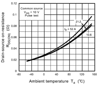
Differences in the on-resistance RDS(on) of elements connected in parallel, or differences in the resistance of the board or wiring, can cause an imbalance in the drain current, which can destroy the elements. This difference in drain current also affects the current value and transient loss during switching. The on-resistance RDS(on) of a MOSFET has a positive temperature coefficient (see Fig. 1). Therefore, even if there is a temperature difference between devices, the risk due to heat generation conditions are not particularly large, because the current flowing to the hotter device is suppressed. Measures include the following:
- Use MOSFETs with no RDS(on) variation, such as using products from the same lot.
- Optimize the board layout (match the resistance components of the wiring).
Countermeasures for imbalance during switching (transient state)
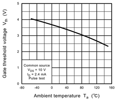
When a device is switching (transient state), in addition to the unbalance factors in the steady state, an imbalance in the drain current occurs due to the difference in Vth of devices connected in parallel and the difference in inductance components of the board and wiring. Also, because Vth has a negative temperature coefficient (see Fig. 2), the Vth of an element whose temperature has risen drops further. This causes further current imbalance. Also, parallel connection can cause not only current imbalance but also oscillation. Countermeasures include the following.
- Use MOSFETs with no Vth variation, such as using products from the same lot.
- Optimize the board layout (match the resistance and inductance components of the wiring).
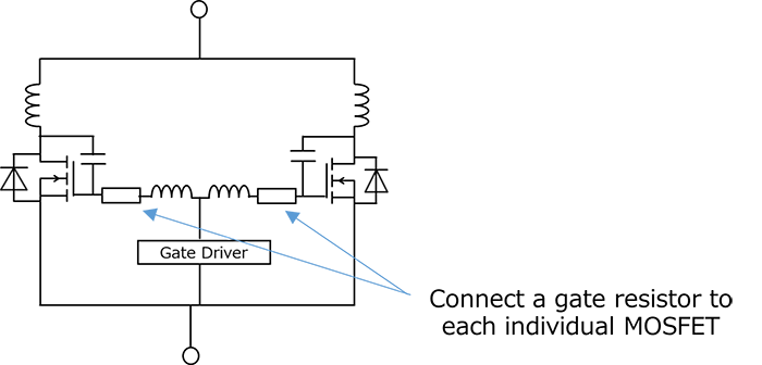
- Insert a series resistor in the gate of each MOSFET to prevent oscillation. *1 (Fig. 3)
- Match the heat dissipation conditions of each element.
In addition, overshoot during switching can cause the MOSFET to break down. In this case, caution is required as product variations can cause all the current to concentrate on an element with a low drain withstand voltage, destroying it.
The following application note also contains information on oscillation, etc. Please refer to it.
When connecting MOSFETs in parallel in this way, care must be taken, just as with bipolar transistors (BJTs). When it comes to imbalance in the steady state, MOSFETs are less likely to experience thermal runaway than BJTs because the temperature characteristic of their on-resistance is positive. However, because MOSFETs have fast switching speeds, more care must be taken with imbalance during switching than with BJTs.
*1: Compared to using a single power MOSFET, parasitic oscillation is more likely to occur when used in parallel. Even if oscillation does not occur, oscillating waveforms such as overshoot and undershoot may be seen at the gate. This is caused by voltage oscillation due to drain wiring inductance during switching (especially when turning off), and a resonant circuit caused by the gate-drain capacitance and gate wiring inductance. Parasitic oscillation can be suppressed by connecting a resistor to the gate of each MOSFET connected in parallel. This countermeasure is also effective in preventing overshoot. See Fig. 3.
Related Links
The following documents also contain related information.
Parametric Search
MOSFETs
FAQs
* Company names, product names, and service names used in this FAQ may be of their respective companies.