
- General Top
- SEMICONDUCTOR
- STORAGE
- COMPANY
-
My ToshibaSemicon
- Semiconductor Top
-
ApplicationsAutomotive
Body Electronics
xEV
In-Vehicle Infotainment
Advanced Driver-Assistance Systems (ADAS)
Chassis
IndustrialInfrastructure
BEMS/HEMS
Factory Automation
Commercial Equipment
Consumer/PersonalIoT Equipment
Healthcare
Wearable Device
Mobile
Computer Peripherals
-
ProductsAutomotive Devices
Discrete Semiconductor
Diodes
Transistors
Logic ICs
Analog Devices
- Automotive SmartMCD™ (Integreted SoC Conbining Microcontroller and Driver)
- Automotive Brushless Motor Driver ICs
- Automotive Brushed DC Motor Driver ICs
- Automotive Stepping Motor Driver ICs
- Automotive Driver ICs
- Automotive System Power Supplies ICs
- Automotive audio power amplifier ICs
- Automotive Network Communication
Digital Devices
Wireless Devices
※
 : Products list (parametric search)Power Semiconductors
SiC Power Devices
※
: Products list (parametric search)Isolators/Solid State RelaysPhotocouplers
Digital Isolators
Solid State Relays
Fiber Optic Transmitting Modules
※
: Products list (parametric search)MOSFETsIGBTs/IEGTsBipolar Transistors※
: Products list (parametric search)Diodes※
: Products list (parametric search)MicrocontrollersMotor Driver ICsIntelligent Power ICs※
: Products list (parametric search)Power Management ICsLinear ICs※
: Products list (parametric search)General Purpose Logic ICsLinear Image SensorsOther Product ICsOther Product ICs
※
: Products list (parametric search) -
Design & Development
Design & Development
Innovation Centre
At the Toshiba Innovation Centre we constantly strive to inspire you with our technologies and solutions. Discover how to place us at the heart of your innovations.
-
Knowledge
Knowledge
Highlighted Topics
Further Materials
Other
- Where To Buy


- Part Number & Keyword Search
- Cross Reference Search
- Parametric Search
- Stock Check & Purchase
This webpage doesn't work with Internet Explorer. Please use the latest version of Google Chrome, Microsoft Edge, Mozilla Firefox or Safari.
require 3 characters or more. Search for multiple part numbers fromhere.
The information presented in this cross reference is based on TOSHIBA's selection criteria and should be treated as a suggestion only. Please carefully review the latest versions of all relevant information on the TOSHIBA products, including without limitation data sheets and validate all operating parameters of the TOSHIBA products to ensure that the suggested TOSHIBA products are truly compatible with your design and application.Please note that this cross reference is based on TOSHIBA's estimate of compatibility with other manufacturers' products, based on other manufacturers' published data, at the time the data was collected.TOSHIBA is not responsible for any incorrect or incomplete information. Information is subject to change at any time without notice.
require 3 characters or more.
Cooling simulation model: Expanding the number of Simplified CFD Models for three-dimensional thermal fluid analysis in MOSFETs
Importance of thermal analysis
In recent years, the size reduction in electronic equipment, high-density mounting, and severe operating conditions such as high ambient temperatures have caused a variety of heat issues when selecting, placing electronic components to be used and designing boards. Therefore, the importance of thermal design using cooling simulation with three forms of heat transfer: thermal conduction, thermal convection, and thermal radiation, is increasing.
Thermal models, such as the enclosure, the board, and the mounted components are required for cooling simulations. Toshiba Electronic Devices & Storage Corporation ("Toshiba") has created the Simplified CFD Model that is suitable for cooling simulations, focusing on MOSFET, and has started releasing this model. Simplified CFD Model can be used with thermal fluid analysis tool to visualize three-dimensional behavior (temperature distribution and flow velocity).
Simplified CFD Model
- CFD is the abbreviation for Computational Fluid Dynamics. In this page, it means three-dimensional thermal fluid analysis.
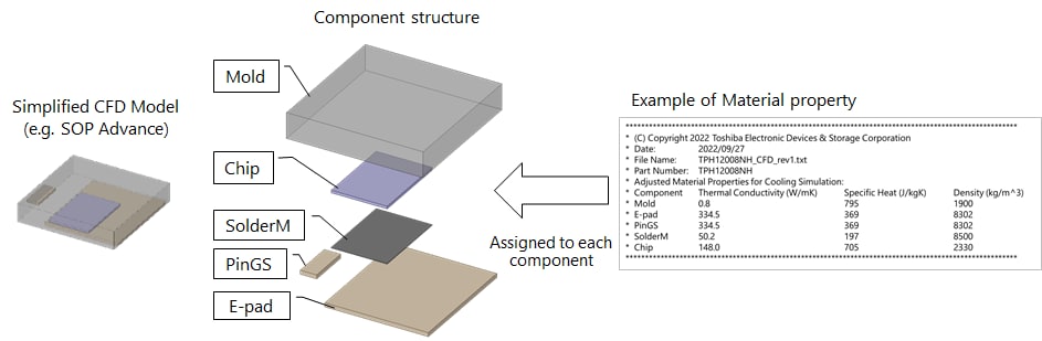
- The device model is a three-dimensional model for this CFD. It simplifies actual components shapes that affect the heat-flow path to the block-shaped structure. (Refer to the left side of Figure 1.)
- Material properties of components provided together with the device model are adjusted from the general values. (Refer to the right side of Figure 1.)
- Model file formats are ISO standard STEP formats, so they are compatible with many 3D CAD tools. They are available in a variety of thermal fluid analysis tools.
Please refer to the application note for the usage of the Simplified CFD Model.
Example of analysis using Simplified CFD Model

Figure 2 shows a simulation result of which losses are applied to a MOSFET and heat is generated. It shows heat spread to the board and heatsink as MOSFET temperature rises.
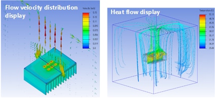
Figure 3 shows the air velocity and heat flow in the chamber set during the analysis. The flow velocity and path of fluid (air) around the board can be checked.
Please refer to the following web page for the list of MOSFETs with Simplified CFD Model.
Related Links

Thermal Management for Designs Using Discrete Semiconductor Devices
There are several effective ways to manage the high temperatures of today’s discrete semiconductors in your design.