
-
My ToshibaSemicon
- 반도체 탑
-
애플리케이션Automotive
Body Electronics
xEV
In-Vehicle Infotainment
Advanced Driver-Assistance Systems (ADAS)
Chassis
IndustrialInfrastructure
BEMS/HEMS
Factory Automation
Commercial Equipment
Consumer/PersonalIoT Equipment
Healthcare
Wearable Device
Mobile
Computer Peripherals
-
제품자동차 디바이스
Discrete Semiconductor
다이오드
트랜지스터
로직 IC
Analog Devices
Digital Devices
Wireless Devices
※
 : Products list (parametric search)파워반도체
※
: Products list (parametric search)Isolators/Solid State RelaysPhotocouplers
Digital Isolators
Solid State Relays
Fiber Optic Transmitting Modules
※
: Products list (parametric search)MOSFETsIGBTs/IEGTs바이폴라 트랜지스터※
: Products list (parametric search)다이오드※
: Products list (parametric search)마이크로컨트롤러모터 드라이버 ICIntelligent Power ICs※
: Products list (parametric search)전원관리IC리니어 IC※
: Products list (parametric search)범용로직IC리니어 이미지 센서기타 제품용 IC기타 제품용 IC
※
: Products list (parametric search) -
개발/설계 지원
-
기술 자료
- 구매처


- 부품 번호 & 키워드 검색
- 상호 참조 검색
- 파라미터 검색
- 재고 확인 및 구매
This webpage doesn't work with Internet Explorer. Please use the latest version of Google Chrome, Microsoft Edge, Mozilla Firefox or Safari.
3글자 이상 입력하세요. Search for multiple part numbers fromhere.
The information presented in this cross reference is based on TOSHIBA's selection criteria and should be treated as a suggestion only. Please carefully review the latest versions of all relevant information on the TOSHIBA products, including without limitation data sheets and validate all operating parameters of the TOSHIBA products to ensure that the suggested TOSHIBA products are truly compatible with your design and application.Please note that this cross reference is based on TOSHIBA's estimate of compatibility with other manufacturers' products, based on other manufacturers' published data, at the time the data was collected.TOSHIBA is not responsible for any incorrect or incomplete information. Information is subject to change at any time without notice.
3글자 이상 입력하세요.
Please explain hard switching and soft switching using IGBTs.
Hard switching and soft switching are switching technologies used in power conversion devices such as inverters and converters, and switching power supplies. They are classified based on the relationship between current and voltage when switching on and off. Soft switching is a technology developed to improve the problems associated with hard switching, such as switching loss and noise (including EMI) on power lines.
Hard switching
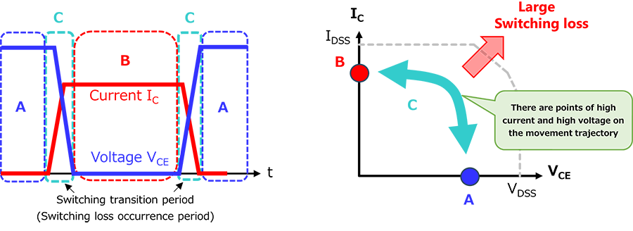
Hard switching is a method of simply turning a switching device on and off (a method of forcibly cutting off current using the device's own cutting-off capability). The switching operation waveform and operation trajectory are shown in Fig. 1. During on/off switching (the switching transition period), both voltage and current are applied to the device, and it changes abruptly from on to off or off to on. This causes surge voltages, switching noise, and large switching losses. This method is applied to simple switch applications, inverter devices for motor drives, switching power supplies, etc.

Soft switching
Soft switching uses an LC resonant circuit to switch the device on and off when the current or voltage is zero. Typical operating waveforms and operating locus are shown in Fig. 2. Representative methods include ZCS (Zero Current Switching), which uses a series LC circuit to perform switching when the current is zero, and ZVS (Zero Voltage Switching), which uses a parallel LC circuit to perform switching when the voltage is zero. Because the element turns on and off when the voltage or current is close to zero, noise and loss associated with switching are small. Representative soft switching applications of IGBTs include induction rice cookers, cooking appliances, and microwave ovens. Also, as can be seen from the fig, the soft switching method places a smaller load on the device in terms of the safe operating area (SOA) compared to hard switching, improving reliability.
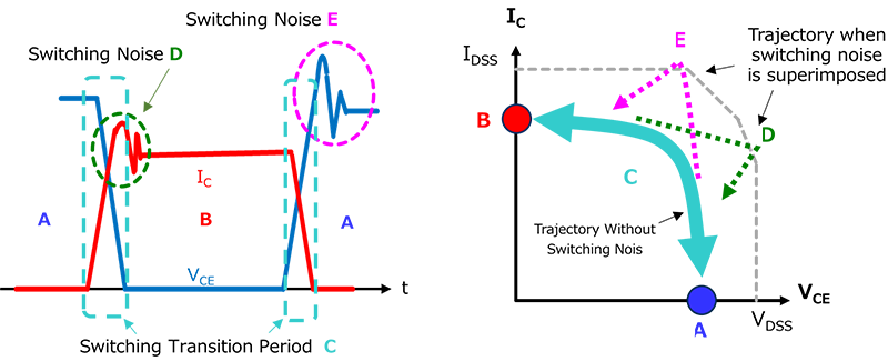
In both hard switching and soft switching, switching noise caused by surges and other factors occurs during the on/off transition (Fig. 3).
- Turn on: Switching noise E is superimposed on the current IC, and the operating locus is
A → E → B.
- Turn off: Switching noise D is superimposed on the voltage VCE, and the operating locus is
B → D → A.
This may result in the maximum ratings or safe operating area (SOA) being exceeded, so check is required.
Soft switching is also explained in the following FAQ:
Related Links
The following documents also contain related information.
파라미터 검색
IGBT/IEGT
자주 있는 문의
* Company names, product names, and service names used in this FAQ may be of their respective companies.