
-
My ToshibaSemicon
- 반도체 탑
-
애플리케이션Automotive
Body Electronics
xEV
In-Vehicle Infotainment
Advanced Driver-Assistance Systems (ADAS)
Chassis
IndustrialInfrastructure
BEMS/HEMS
Factory Automation
Commercial Equipment
Consumer/PersonalIoT Equipment
Healthcare
Wearable Device
Mobile
Computer Peripherals
-
제품자동차 디바이스
Discrete Semiconductor
다이오드
트랜지스터
로직 IC
Analog Devices
Digital Devices
Wireless Devices
※
 : Products list (parametric search)파워반도체
※
: Products list (parametric search)Isolators/Solid State RelaysPhotocouplers
Digital Isolators
Solid State Relays
Fiber Optic Transmitting Modules
※
: Products list (parametric search)MOSFETsIGBTs/IEGTs바이폴라 트랜지스터※
: Products list (parametric search)다이오드※
: Products list (parametric search)마이크로컨트롤러모터 드라이버 ICIntelligent Power ICs※
: Products list (parametric search)전원관리IC리니어 IC※
: Products list (parametric search)범용로직IC리니어 이미지 센서기타 제품용 IC기타 제품용 IC
※
: Products list (parametric search) -
개발/설계 지원
-
기술 자료
- 구매처


- 부품 번호 & 키워드 검색
- 상호 참조 검색
- 파라미터 검색
- 재고 확인 및 구매
This webpage doesn't work with Internet Explorer. Please use the latest version of Google Chrome, Microsoft Edge, Mozilla Firefox or Safari.
3글자 이상 입력하세요. Search for multiple part numbers fromhere.
The information presented in this cross reference is based on TOSHIBA's selection criteria and should be treated as a suggestion only. Please carefully review the latest versions of all relevant information on the TOSHIBA products, including without limitation data sheets and validate all operating parameters of the TOSHIBA products to ensure that the suggested TOSHIBA products are truly compatible with your design and application.Please note that this cross reference is based on TOSHIBA's estimate of compatibility with other manufacturers' products, based on other manufacturers' published data, at the time the data was collected.TOSHIBA is not responsible for any incorrect or incomplete information. Information is subject to change at any time without notice.
3글자 이상 입력하세요.
Half-bridge DC-DC Converter Scheme Shrinks Power in Data Centers
To reduce power consumption, data centers are embracing new rack architectures based on 48 V bus voltages. Learn how to design a half-bridge DC-DC converter to implement such a 48 V system.
Introduction
The pressure on to scale up and build new data centers (Figure 1) to meet the increasing demands for data storage. This expansion is ultimately resulting in greater power consumption, along with demands for reducing the power loss.
One highly effective way of reducing the power consumption of a data center is to use the 48 V bus voltage for server racks. That said, such architectures are only practical by using carefully selected highly efficient MOSFETs.

Chapter 1: How Open Rack Architecture Addresses Power Loss
To achieve better efficiency, power losses must be dealt with. The Open Rack architecture proposed by the Open Compute Project (OCP) addresses loss of power by using 48 V bus lines rather than conventional 12 V bus lines.
To understand how this works, start by recalling that the power loss caused by a power line is calculated using I2R, where R is the power line resistance, and I is the power line current. Based on this simple relationship between current and resistance, a lower current leads for the same level of resistance will lead to less power loss and more efficiency.
In the case of Open Rack architecture, consider the power loss when the same amount of power is supplied to server racks through 12 V bus lines vs. 48 V bus lines: the current that passes through a 48 V bus line is only 1/4 the current that passes through a 12 V bus line. Therefore, assuming the 48 V and 12 V bus lines have the same level of resistance, the 48 V bus will lose 1/16 the power of the 12 V one.
Reference links:
Chapter 2: Open Rack Using a Half-Bridge DC-DC Converter
To go beyond the theory and to the practical application of Open Rack architecture, consider using a half-bridge DC-DC converter such as that shown in Figure 2. Such a converter can efficiently step down the 48 V bus line voltage to 1.2 V and reduce total system power consumption.
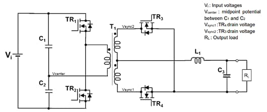
Elements of power loss due to MOSFET operation on the half-bridge DC-DC converter are gate drive loss, output capacitance loss, diode reverse recovery loss, and conduction loss in addition to switching loss. Each element impacts DC-DC converter efficiency.
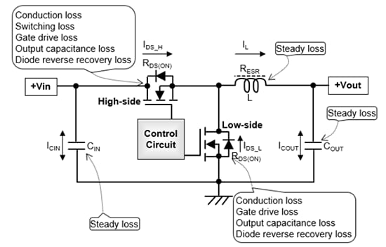
To simplify the consideration, we use non-isolated buck DC-DC converter which is configured with two MOSFETs as shown in Figure 3 instead of the half-bridge DC-DC converter. When the power loss of half-bridge DC-DC converter is considered, the high-side MOSFET in Figure 3 corresponds to the primary side MOSFETs in Figure 2 (TR1, TR2) and the low-side MOSFET in Figure 3 corresponds to the secondary MOSFETs in Figure 2 (TR3, TR4).
The power losses shown in Figure 3 are generated on each MOSFET of the non-isolated buck DC-DC converter. These losses can be reduced drastically by using an appropriate MOSFET.
Chapter 3: Our Approach
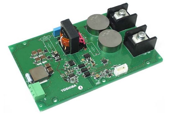
We have developed a reference design of half-bridge DC-DC converter which supports the 48 V bus system and have investigated the most effective and practical power MOSFETs needed to achieve the highest efficiency level on the 48 V bus system.
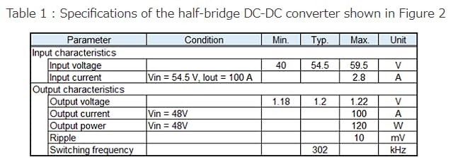
Table 1 shows specification of the half-bridge DC-DC converter and Figure 5 shows a block diagram of the converter.
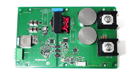
By using appropriate MOSFETs, the half-bridge DC-DC converter achieves total efficiency of 92.8 % (Vin = 54.5 V, 30 % load) with just 160 mm x 100 mm board size.
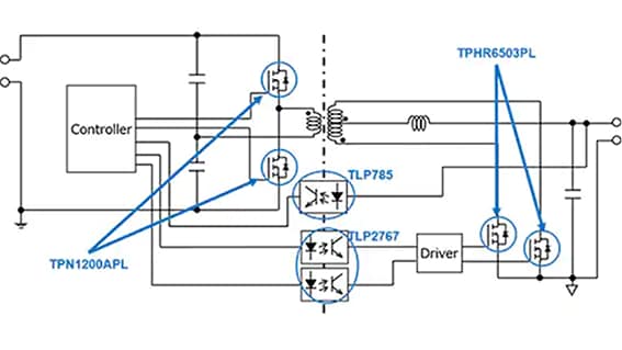
Although the smaller input capacitance MOSFET the better in switching loss, which has a big impact on the primary side, standpoint, an impact of conduction loss cannot be ignored because average of around 3 A current flows at the maximum load. Therefore, we have selected TPN1200APL which has good balance of input capacitance value and drain-source on-resistance.
On the secondary side, the built-in diodes will operate before the MOSFETs turn on, making conduction losses dominant. Therefore, we have selected TPHR6503PL which has the lowest drain-source on-resistance of 0.41 mΩ among our 30 V MOSFET lineup.
Chapter 4: All About Reducing Power Consumption
The Open Rack architecture proposed by OCP uses 48 V lines to reduce power consumption and improve efficiency. The half-bridge DC-DC converter supporting the 48 V bus system is one approach to efficient implementation.
DC-DC converters require careful selection of MOSFETs to be effective. We have selected TPN1200APL for the primary side MOSFET and TPHR6503PL for the secondary side MOSFET on the compact and highly efficient DC-DC converter reference design.
We offer high-quality and highly efficient MOSFETs with VDSS ranging from 30 V to 250 V, as well as various drain-source on-resistance types in each VDSS class, so engineers can find the right MOSFET when designing a DC-DC converter.
Reference links:
More detailed information such as products, block diagrams, board information, usage instructions, etc. can be found below.


Download PDF
Please click the button to download the PDF file.