
-
My ToshibaSemicon
- 반도체 탑
-
애플리케이션Automotive
Body Electronics
xEV
In-Vehicle Infotainment
Advanced Driver-Assistance Systems (ADAS)
Chassis
IndustrialInfrastructure
BEMS/HEMS
Factory Automation
Commercial Equipment
Consumer/PersonalIoT Equipment
Healthcare
Wearable Device
Mobile
Computer Peripherals
-
제품자동차 디바이스
Discrete Semiconductor
다이오드
트랜지스터
로직 IC
Analog Devices
Digital Devices
Wireless Devices
※
 : Products list (parametric search)파워반도체
※
: Products list (parametric search)Isolators/Solid State RelaysPhotocouplers
Digital Isolators
Solid State Relays
Fiber Optic Transmitting Modules
※
: Products list (parametric search)MOSFETsIGBTs/IEGTs바이폴라 트랜지스터※
: Products list (parametric search)다이오드※
: Products list (parametric search)마이크로컨트롤러모터 드라이버 ICIntelligent Power ICs※
: Products list (parametric search)전원관리IC리니어 IC※
: Products list (parametric search)범용로직IC리니어 이미지 센서기타 제품용 IC기타 제품용 IC
※
: Products list (parametric search) -
개발/설계 지원
-
기술 자료
- 구매처


- 부품 번호 & 키워드 검색
- 상호 참조 검색
- 파라미터 검색
- 재고 확인 및 구매
This webpage doesn't work with Internet Explorer. Please use the latest version of Google Chrome, Microsoft Edge, Mozilla Firefox or Safari.
3글자 이상 입력하세요. Search for multiple part numbers fromhere.
The information presented in this cross reference is based on TOSHIBA's selection criteria and should be treated as a suggestion only. Please carefully review the latest versions of all relevant information on the TOSHIBA products, including without limitation data sheets and validate all operating parameters of the TOSHIBA products to ensure that the suggested TOSHIBA products are truly compatible with your design and application.Please note that this cross reference is based on TOSHIBA's estimate of compatibility with other manufacturers' products, based on other manufacturers' published data, at the time the data was collected.TOSHIBA is not responsible for any incorrect or incomplete information. Information is subject to change at any time without notice.
3글자 이상 입력하세요.
3rd generation SiC MOSFETs with New package TO-247-4L(X) released
Compared to Si (silicon) IGBTs and MOSFETs, which are currently mainstream, power MOSFETs using SiC (silicon carbide) not only excel in low conduction loss and operation in high-temperature environments, but also contribute to low-loss application through high-speed switching.
TO-247-4L(X), a new package for our 3rd generation SiC MOSFETs, is a 4-terminal type, and by reducing the influence of the inductance of the source wire inside the package, it is possible to draw out high-speed switching performance. This contributes to lower loss in applications such as servers, uninterruptible power supplies (UPS), and Photovoltaics Inverter.
Below is a comparison of features and switching loss reduction effects for our new package TO-247-4L(X) (4-terminal type) and our existing product TO-247 (3-terminal type).
Features of TO-247-4L(X) package
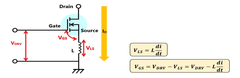
In the three-terminal type, As shown in Fig. 1, when the gate drive voltage VDRV is applied, the inductance component L of the source wire and the gradient dID / dt component of the drain current ID generate a counter electromotive voltage VLS.
Therefore, the gate drive voltage VDRV is reduced by the back electromotive voltage VLS. The voltage VGS applied between the gate and source of the FET chip is the gate drive voltage VDRV reduced by the counter electromotive voltage VLS. This slows down the switching speed of SiC MOSFETs.
On the other hand, As shown in Fig. 2, 4-terminal type reduces the effect of back electromotive voltage VLS by connecting the signal source terminal for gate drive close to the FET chip. As a result, in the 4-terminal type, the voltage VGS applied between the gate and source and the gate drive voltage VDRV are approximately the same value, and the switching speed of the SiC MOSFET is improved compared to the 3-terminal type.

Switching loss reduction effect
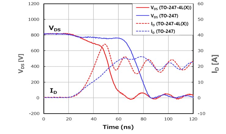
Fig. 3 shows the turn-on switching waveforms of the 4-terminal type and the 3-terminal type by inductive load switching. At turn-on, the drain current ID (dotted red line) of the 4-terminal type rises steeper than the drain current ID (dotted blue line) of the 3-terminal type.
This is because the 4-terminal type shown in Fig. 2 reduces the influence of the inductance of the source wire compared to the 3-terminal type, and it suppresses lowering the gate drive voltage during switching. Therefore, the 4-terminal type has a faster turn-on speed than the 3-terminal type.
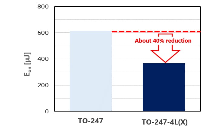
Fig.4 also shows the turn-on loss Eon of 4-terminal type and 3-terminal type. The turn-on loss Eon of 4-terminal type is approximately 40% lower than that of the 3-terminal type.
Measurement condition
VDD = 800 V, VGS = 18 V / 0 V, ID = 20 A, Ta = 25 ℃, L=100 μH, Rg (external gate resistor) = 4.7 Ω
The freewheeling diode uses the diode between the source and drain of each product.
(Toshiba internal comparison, as of July 2023)
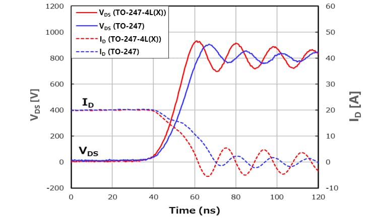
Fig. 5 shows turn-off switching waveforms for 4-terminal and 3-terminal types due to inductive load switching. At turn-off, the drain current ID (dotted red line) of the 4-terminal type decreases faster than the drain current ID (dotted blue line) of the 3-terminal type. In other words, the 4-terminal type turns off is faster than the 3-terminal type.
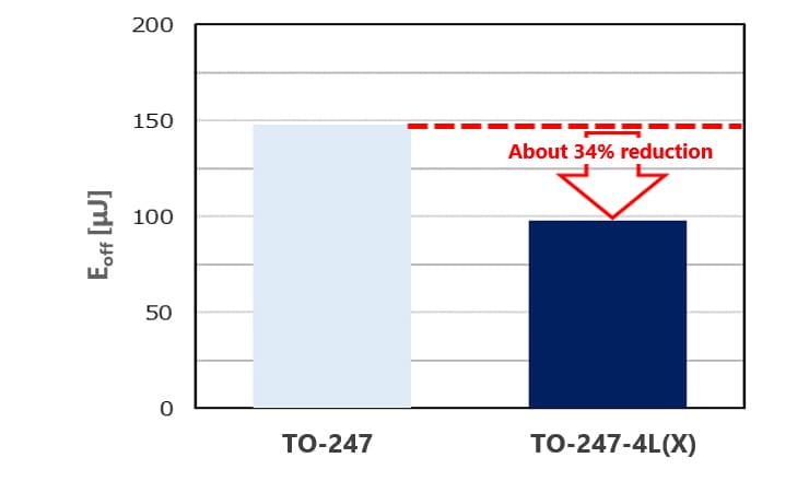
Fig. 6 also shows the turn-off loss Eoff for the 4-terminal type and 3-terminal type. The turn-off loss Eoff of the 4-terminal type is approximately 34% lower than the turn-off loss Eoff of the 3-terminal type.
Measurement condition
VDD = 800 V, VGS = 18 V / 0 V, ID = 20 A, Ta = 25 ℃, L=100 μH, Rg (external gate resistor) = 4.7 Ω
The freewheeling diode uses the diode between the source and drain of each product.
(Toshiba internal comparison, as of July 2023)
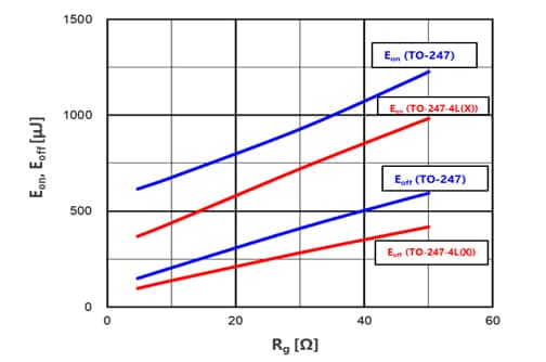
To summarize the above, Fig. 7 shows the relationship between turn-on loss Eon and turn-off loss Eoff with respect to external gate resistance Rg for 4-terminal and 3-terminal types.
- Both the 4-terminal type and the 3-terminal type tend to increase turn-on loss Eon and turn-off loss Eoff as the external gate resistance Rg increases.
- The 4-terminal type has smaller turn-on loss Eon and turn-off loss Eoff than the 3-terminal type.
Measurement condition
VDD = 800 V, VGS = 18 V / 0 V, ID = 20 A, Ta = 25 ℃, L=100 μH, Rg (external gate resistor) = 4.7 Ω
The freewheeling diode uses the diode between the source and drain of each product.
(Toshiba internal comparison, as of June 2023)
Related information
See the following page for the reference design.
Reference design
See the following pages for application examples for various applications.
Server
Uninterruptible Power Supply
LED Lighting
See the page below for packages details.
packages
see the following page for related news releases.
Release of 3rd Generation SiC MOSFETs TO-247-4L(X) package product that contributes to power efficiency of industrial application
Toshiba’s New Device Structure Improves SiC MOSFET Reliability
Toshiba’s New SiC MOSFETs Delivers Low On-Resistance and Significantly Reduced Switching Loss
자주 있는 문의
See the following page for frequently asked questions.
MOSFETs
Simulation Model
You can use various simulation models.
* PSpice® is a registered trademark of Cadence Design Systems, Inc.
* LTspice® is simulation software and registered trademarks of Analog Devices, Inc.
* SIMetrix® is simulation software and registered trademarks of SIMetrix Technologies Ltd.
* Other company names, product names, and service names may be trademarks of their respective companies.
Queries about purchasing, sampling and IC reliability
재고 확인 및 구매
3글자 이상 입력하세요.
Through this website you are able to proceed to the website of our distributors ("Third Party Website") which is not under the control of Toshiba Corporation and its subsidiaries and affiliates (collectively "Toshiba"). The Third Party Website is made available to you as a convenience only and you agree to use the Third Party Website at your own risk. The link of the Third Party Website does not necessarily imply a recommendation or an endorsement by Toshiba of the Third Party Website. Please be aware that Toshiba is not responsible for any transaction done through the Third Party Website, and such transactions shall be subject to terms and conditions which may be provided in the Third Party Website.