
- General Top
- SEMICONDUCTOR
- STORAGE
- COMPANY
-
My ToshibaSemicon
- Semiconductor Top
-
ApplicationsAutomotive
Body Electronics
xEV
In-Vehicle Infotainment
Advanced Driver-Assistance Systems (ADAS)
Chassis
IndustrialInfrastructure
BEMS/HEMS
Factory Automation
Commercial Equipment
Consumer/PersonalIoT Equipment
Healthcare
Wearable Device
Mobile
Computer Peripherals
-
ProductsAutomotive Devices
Discrete Semiconductor
Diodes
Transistors
Logic ICs
Analog Devices
Digital Devices
Wireless Devices
※
 : Products list (parametric search)Power Semiconductors
SiC Power Devices
※
: Products list (parametric search)Isolators/Solid State RelaysPhotocouplers
Digital Isolators
Solid State Relays
Fiber Optic Transmitting Modules
※
: Products list (parametric search)MOSFETsIGBTs/IEGTsBipolar Transistors※
: Products list (parametric search)Diodes※
: Products list (parametric search)MicrocontrollersMotor Driver ICsIntelligent Power ICs※
: Products list (parametric search)Power Management ICsLinear ICs※
: Products list (parametric search)General Purpose Logic ICsLinear Image SensorsOther Product ICsOther Product ICs
※
: Products list (parametric search) -
Design & Development
-
Knowledge
- Where To Buy


- Part Number & Keyword Search
- Cross Reference Search
- Parametric Search
- Stock Check & Purchase
This webpage doesn't work with Internet Explorer. Please use the latest version of Google Chrome, Microsoft Edge, Mozilla Firefox or Safari.
require 3 characters or more. Search for multiple part numbers fromhere.
The information presented in this cross reference is based on TOSHIBA's selection criteria and should be treated as a suggestion only. Please carefully review the latest versions of all relevant information on the TOSHIBA products, including without limitation data sheets and validate all operating parameters of the TOSHIBA products to ensure that the suggested TOSHIBA products are truly compatible with your design and application.Please note that this cross reference is based on TOSHIBA's estimate of compatibility with other manufacturers' products, based on other manufacturers' published data, at the time the data was collected.TOSHIBA is not responsible for any incorrect or incomplete information. Information is subject to change at any time without notice.
require 3 characters or more.
Considerations for board design
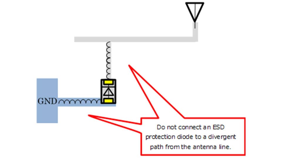
Even the optimum ESD protection diode does not provide any beneficial effects unless a printed circuit board is properly designed.
The following considerations apply to the board design:
- Connect an ESD protection diode directly to a board trace leading to the DUP. Do not connect an ESD protection diode to a divergent path from the antenna line because such a trace has undesired inductance, increasing the impedance of the path to the ESD protection diode.
- The above guideline also applies to GND. Connect an ESD protection diode to the GND plane.
16-QAM/64-QAM
Modern telecommunication systems use 16-QAM, 64-QAM or other modulation methods in order to satisfy the requirement for high-speed communication. Quadrature amplitude modulation (QAM) transmits information by modulating both the amplitude and phase of two carrier waves. In QAM, the constellation points are usually arranged in a square grid as shown in Figure 7 instead of a concentric grid. Although QAM provides high spectral information density, it is susceptible to noise and waveform distortion.
Modulation methods are broadly divided into amplitude-shift keying (ASK), phase-shift keying (PSK), frequency-shift keying (FSK), and quadrature amplitude modulation (QAM).
Accompanying a shift from analog data to digital data, many communication standards have adopted a modulation method called quadrature phase-shift keying (QPSK). QPSK uses a constant amplitude level and four phase levels. It transmits information as one of four symbols, each representing two bits of data. To further increase the spectral information density, migrations to higher QAM channel counts such as 16-QAM and 64-QAM are in progress. 16-QAM uses four amplitude levels along two orthogonal directions and transmits information as one of 16 symbols, each representing four bits of data. 64-QAM uses eight amplitude levels along two orthogonal directions and transmits information as one of 64 symbols, each representing six bits of data.
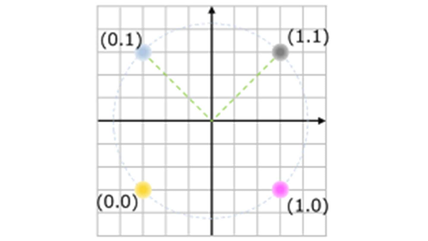

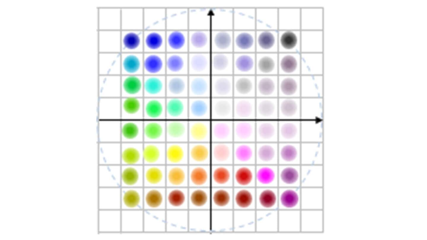
Figure 7 Modulation methods
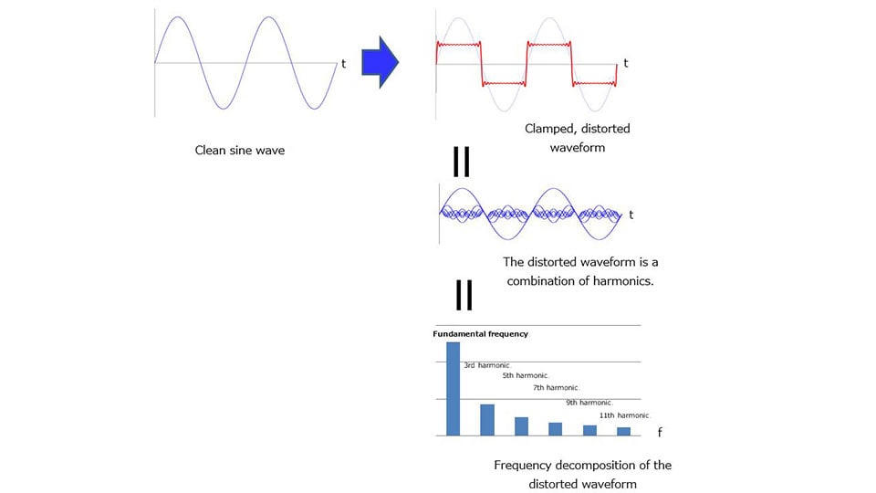
Harmonic distortion
Harmonic distortion is amplitude distortion caused by system nonlinearities. It occurs when the gain of an amplifier varies with input voltage and when an input waveform is clamped.
For example, a clean sine wave contains only a fundamental harmonic. Suppose that the fundamental harmonic is clamped by a circuit. This causes harmonic distortion. The harmonic frequency becomes an integer multiple of the fundamental frequency. In Figure 8, clamping generates an odd-order harmonic because the sine wave is equally clamped on the positive and negative sides. Even-order harmonics occur, depending on the waveform distortion.