
- General Top
- SEMICONDUCTOR
- STORAGE
- COMPANY
-
My ToshibaSemicon
- Semiconductor Top
-
ApplicationsAutomotive
Body Electronics
xEV
In-Vehicle Infotainment
Advanced Driver-Assistance Systems (ADAS)
Chassis
IndustrialInfrastructure
BEMS/HEMS
Factory Automation
Commercial Equipment
Consumer/PersonalIoT Equipment
Healthcare
Wearable Device
Mobile
Computer Peripherals
-
ProductsAutomotive Devices
Discrete Semiconductor
Diodes
Transistors
Logic ICs
Analog Devices
Digital Devices
Wireless Devices
※
 : Products list (parametric search)Power Semiconductors
SiC Power Devices
※
: Products list (parametric search)Isolators/Solid State RelaysPhotocouplers
Digital Isolators
Solid State Relays
Fiber Optic Transmitting Modules
※
: Products list (parametric search)MOSFETsIGBTs/IEGTsBipolar Transistors※
: Products list (parametric search)Diodes※
: Products list (parametric search)MicrocontrollersMotor Driver ICsIntelligent Power ICs※
: Products list (parametric search)Power Management ICsLinear ICs※
: Products list (parametric search)General Purpose Logic ICsLinear Image SensorsOther Product ICsOther Product ICs
※
: Products list (parametric search) -
Design & Development
-
Knowledge
- Where To Buy


- Part Number & Keyword Search
- Cross Reference Search
- Parametric Search
- Stock Check & Purchase
This webpage doesn't work with Internet Explorer. Please use the latest version of Google Chrome, Microsoft Edge, Mozilla Firefox or Safari.
require 3 characters or more. Search for multiple part numbers fromhere.
The information presented in this cross reference is based on TOSHIBA's selection criteria and should be treated as a suggestion only. Please carefully review the latest versions of all relevant information on the TOSHIBA products, including without limitation data sheets and validate all operating parameters of the TOSHIBA products to ensure that the suggested TOSHIBA products are truly compatible with your design and application.Please note that this cross reference is based on TOSHIBA's estimate of compatibility with other manufacturers' products, based on other manufacturers' published data, at the time the data was collected.TOSHIBA is not responsible for any incorrect or incomplete information. Information is subject to change at any time without notice.
require 3 characters or more.
Gate-Driver IC for Automotive Three-Phase Brushless Motor: TB9083FTG
Gate driver IC capable of the latest functional safety standards
For three-phase brushless DC motor applications such as electric power steering (EPS) and electric brakes.
Product Highlights
Toshiba Electronic Devices & Storage Corporation ("Toshiba") has launched “TB9083FTG,” a gate driver IC[3] for automotive three-phase brushless DC motors compliant with ISO26262 and supporting safety level ASIL-D[4]. The device drives external MOSFETs to a rotate three-phase brushless DC motor (Figure 1) and can drive the upper and lower MOSFETs for all three-phases, i.e. six MOSFETs. Examples of applications for which the device is suitable are Electric Power Steering or EPS, Electric brakes and Shift-by-Wire.
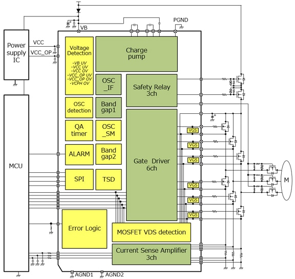
Figure 1: Internal block diagram and example of application circuit
In August 2017, Toshiba previously launched “TB9081FG”, a gate driver compliant with ISO 26262. TB9083FTG was developed by improving “TB9081FG”.
The key improvements are robust functionality through redundancy, ABIST (Analog Built-in Self-test) and LBIST (Built-in Self-test) circuits. These are indispensable for compliance with ISO 26262. In terms of redundancy of functions, two band gap reference voltage circuits are built in as in the TB9081FG, and two clock oscillation circuits (OSC) are newly built in the TB9083FTG. The purpose is to minimize the occurrence of dependent failures. On the other hand, ABIST and LBIST take a role to check whether internal diagnostic functions operate properly. These check results can be read out via SPI communication.
Built-in 3 channels of drivers for safety relays
There are three major improvements made to the TB9083FTG. First is, the inclusion of only three channels of safety relays compared to the five in TB9081. Safety relays take a role to electrically cut off abnormal point of motor or external MOSFET and so on. Based on customer feedback, it was determined that three would be enough to meet their system requirements. In the case of EPS, two channels could be applied to the power supply relay and the reverse polarity protection relay and the other channel could be applied to the motor relay to cut off the control circuit from the motor. (Figure 2)
TB9083FTG Merit (1)
Built-in three channels relay driver for redundant/not redundant
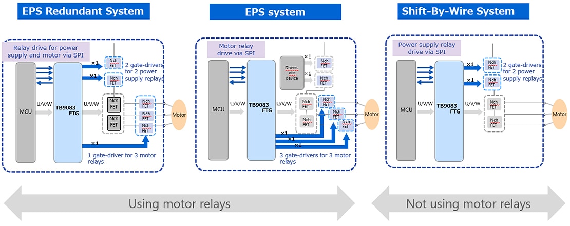
Figure 2: Example of using safety relay
Reducing mounting area reduction (to 66%[1]) by small package adoption
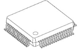
Second feature is the adoption of a VQFN 48pin package with a small PCB mounting area of 7.0mm x 7.0mm (Table 1). Since TB9081FG was a 64-LQFP with 12.0mm x 12.0mm mounting area which includes outer leads, the area is reduced by around half. Selection for the small package is deeply related to ISO 26262, because ISO 26262 might require redundant devices for robust functionality in order to ensure the higher safety level. This redundancy enables the case that a motor can be driven by the other TB9083FTG even if one TB9083FTG has a failure. However, using two devices doubles the mounting area on the PCB. TB9083FTG prevents the increase by adopting a small package.
TB9083FTG Merit (2)
Small package adoption
|
TB9083FTG | TB9081FG | Supplier A |
|---|---|---|---|
| Gate-driver for safety relays |
3ch | 5ch | None |
External resistors for |
Not required | Required | Not required |
| FET Diagnostics | ✔ | None | None |
| Package | VQFN48 | LQFP64 | THQFP48 |
| Drawings |  7mm□ |
 10mm□ (12mm□ including lead frame) |
 7mm□ (9mm□ including lead frame) |
Table 1:Comparison between three devices
In addition, to further reduce required PCB area, the TB9083FTG has built-in resistors to set the gain and the reference voltage of the motor current sense amplifier. These resistor was required externally in TB9081FG. The gain can be set via the serial interface SPI.
Built-in self-diagnostic circuit for external MOSFETs
The third feature is a built-in sequencer and verification circuit to detect open and short faults of the external MOSFETs. TB9083 monitors midpoints of the upper and lower arms of each of the three phases (Figure 3). The microcontroller can read out the diagnostic results via SPI. To implement the same diagnostics, the TB9081FG needed to monitor the motor terminal voltage with a built-in A-D converter (ADC) in the microcontroller and external bias resistors. In addition to eliminating the need to use an A-D converter in the microcontroller (MCU) for this diagnosis, it also has the advantage of reducing the amount of software code. It also eliminates the need for external resistors for diagnostics.
TB9083FTG Merit (3)
Available self-diagnosis for external MOSFETs
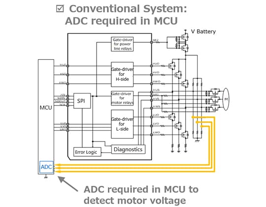
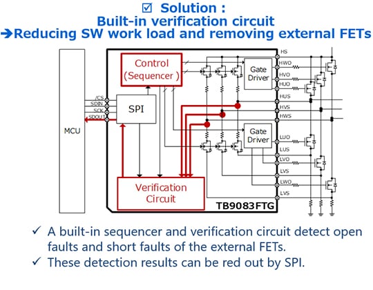
Figure 3:Comparison of conventional system and TB9083FTG’s solution
Verified for 3,000 cycles temperature cycling test
The adopted QFN package employs a wettable flank structure[5]. This enables visual inspection of solder joints using an automatic optical inspection (AOI) system, and contributes to improved solder joint reliability. In addition, Toshiba has verified the package through 3,000 cycles in the mounting temperature cycling test.
3,000 cycles passed
| Category | Item | Test condition |
|---|---|---|
| Temperature cycling | -40℃ to 125℃ |
|
| Not Pass criteria | 10% drift from initial resistive value | |
| IC | Package | VQFN48-0707-0.50 (Wettable Flank) |
| Plating | Sn | |
| PCB | Size | 35mm × 35mm × 1.6mmt |
| Layer | 6 layers | |
| Material | FR-4 | |
| Surface finishing | OSP (Organic Solderability Preservative) | |
| Solder | Paste material | SAC305 |
| Thickness of screen mask | 130um | |
| Peak temperature during reflow processing | 230 to 250℃ | |
| Soldering between E-pad of QFN and PCB | performed | |
Table 2:Result and test condition of mounting temperature cycling test
Toshiba continues to strengthen our line-up of ISO 26262 2nd edition capable gate-driver IC for automotive three-phase brushless DC motor applications Toshiba will continue to contribute to the electrification and safety-improvement of automotive equipment by bringing to market products with optimized functions and performance built into the ICs to meet customer needs.
Notes:
[1] Compared with the Toshiba’s existing product TB9081FG (12.0mm × 12.0mm (typ.))
[2] Functional-safety standards seek to minimize risk resulting from system failures. Specifically, it is important to explain an argument for system safety to third party. A dedicated development process is regulated in ISO 26262 as automotive standard in order to correctly realize functional safety.
[3] Driver to drive MOSFET
[4] ASIL: Automotive Safety Integrity Level, D: Grade D (highest rank of A to D)
[5] Shape of outer leads of package
Related information
Queries about purchasing, sampling and IC reliability
Stock Check & Purchase
require 3 characters or more.