
-
My ToshibaSemicon
- 반도체 탑
-
애플리케이션Automotive
Body Electronics
xEV
In-Vehicle Infotainment
Advanced Driver-Assistance Systems (ADAS)
Chassis
IndustrialInfrastructure
BEMS/HEMS
Factory Automation
Commercial Equipment
Consumer/PersonalIoT Equipment
Healthcare
Wearable Device
Mobile
Computer Peripherals
-
제품자동차 디바이스
Discrete Semiconductor
다이오드
트랜지스터
로직 IC
Analog Devices
Digital Devices
Wireless Devices
※
 : Products list (parametric search)파워반도체
※
: Products list (parametric search)Isolators/Solid State RelaysPhotocouplers
Digital Isolators
Solid State Relays
Fiber Optic Transmitting Modules
※
: Products list (parametric search)MOSFETsIGBTs/IEGTs바이폴라 트랜지스터※
: Products list (parametric search)다이오드※
: Products list (parametric search)마이크로컨트롤러모터 드라이버 ICIntelligent Power ICs※
: Products list (parametric search)전원관리IC리니어 IC※
: Products list (parametric search)범용로직IC리니어 이미지 센서기타 제품용 IC기타 제품용 IC
※
: Products list (parametric search) -
개발/설계 지원
-
기술 자료
- 구매처


- 부품 번호 & 키워드 검색
- 상호 참조 검색
- 파라미터 검색
- 재고 확인 및 구매
This webpage doesn't work with Internet Explorer. Please use the latest version of Google Chrome, Microsoft Edge, Mozilla Firefox or Safari.
3글자 이상 입력하세요. Search for multiple part numbers fromhere.
The information presented in this cross reference is based on TOSHIBA's selection criteria and should be treated as a suggestion only. Please carefully review the latest versions of all relevant information on the TOSHIBA products, including without limitation data sheets and validate all operating parameters of the TOSHIBA products to ensure that the suggested TOSHIBA products are truly compatible with your design and application.Please note that this cross reference is based on TOSHIBA's estimate of compatibility with other manufacturers' products, based on other manufacturers' published data, at the time the data was collected.TOSHIBA is not responsible for any incorrect or incomplete information. Information is subject to change at any time without notice.
3글자 이상 입력하세요.
Can eFuse IC (electronic fuse) be used for hot-swap?
eFuse ICs (electronic fuses) are an effective measure against inrush current, which is a problem when hot-swapping boards and connectors. Furthermore, eFuse IC not only has the inrush current suppression function necessary for this countermeasure, but also has built-in thermal shutdown, short circuit protection function, overvoltage clamp, reverse current blocking, etc., making it possible to build a more robust system.
For communication equipment, network equipment, data center servers, storage systems, etc., workers will replace or expand failed boards and modules, and reconnect cables, etc., while the system is running. Furthermore, with mobile devices such as computer equipment and smartphones, it is common to connect and disconnect cables such as USB and HDMI while the power is on. Adding or removing components while the power is on and without adversely affecting the operation of the system is called hot swapping. Although they may not be exactly the same, hot swapping is sometimes called hot plugging as a synonym.
The following explanation assumes that you are using a hot-swappable staggered connector (socket). This connector is designed with a long GND, so that the GND is the first thing that comes into contact when it is inserted, and the GND is the last to leave when it is removed.

There are two modes of hot swap.
1) Plug in the board or cable while the device is operating.
2) Unplug the board or cable while the device is operating.
If no measures are taken, these operations may cause problems with system operation within the device.
Consider a device that connects and disconnects boards as shown in Fig. 1.
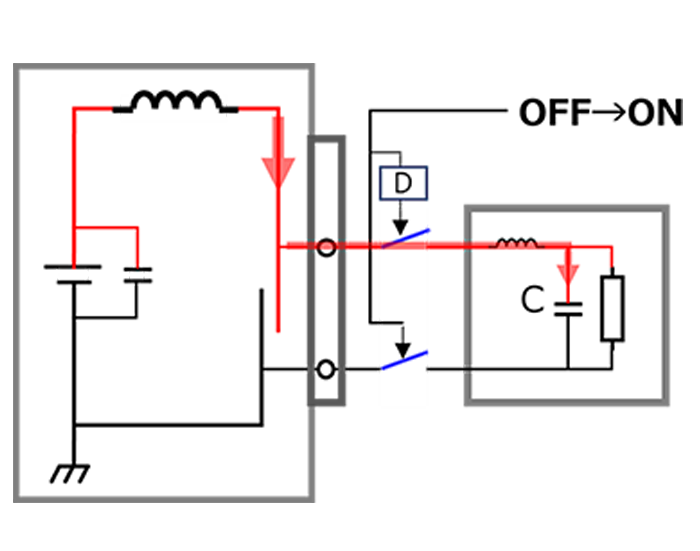
1) Plug in the board
Fig. 2 uses a switch to equivalently represent the state when plugging in. “D” in the diagram represents the contact delay with respect to GND when using a staggered connector.
When power is supplied to the inserted board via the connector, the capacitance C (F), which includes the parasitic capacitance that exists between the board's power line and GND, begins to be charged. If the power supply voltage is V (V), the charging current IC (A) when plugged in is expressed by the following formula.
IC = C x dV / dt
The rise time (dV / dt) varies depending on the impedance of the power supply line and GND line, but if no processing is done, it will try to rise instantly. Therefore, this current (inrush current) is extremely large and may exceed the maximum current value expected in the system. This overcurrent may damage connectors, etc., or cause problems such as a temporary drop in the power supply voltage of the backplane connected to the board, causing other boards, modules, and equipment to be reset.
To accommodate this, it is necessary to insert an element that suppresses inrush current, such as an eFuse IC, into the power supply line. The eFuse IC not only has an inrush current suppression function, but also has built-in thermal shutdown, short circuit protection, over voltage clamp, and reverse current blocking, making it possible to build a more robust system.
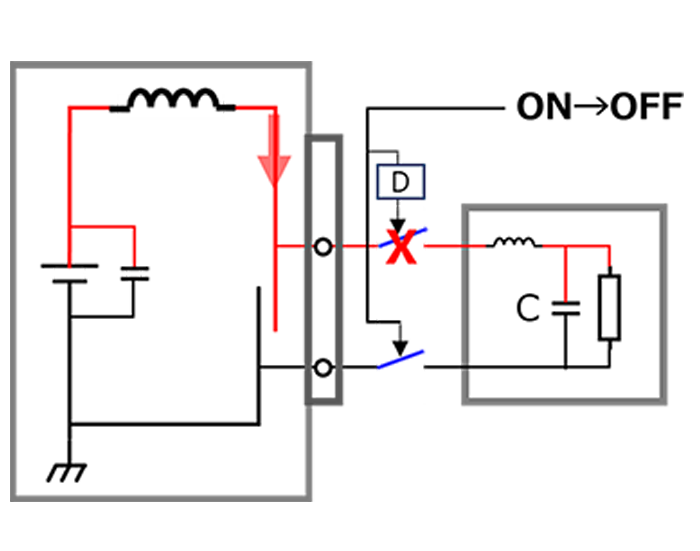
2) Unplug in the board
Fig. 3 uses switches to equivalently represent the state when removing the board.
If you remove the board, the current that was being supplied will also be cut off. On the removed board side, the charge stored in the capacitor is discharged and the circuit stops. It is on the equipment side that the problem may arise. The current that was being supplied to the board you pulled out will suddenly stop. At this time, the parasitic inductor L that exists on the power supply line and GND line generates a self-induced electromotive force to prevent the current from changing. Self-induced electromotive force VL is expressed by the following formula.
VL = - L x dI / dt
Since the current change is a decrease (stop), VL will be superimposed on the power supply voltage VCC. The magnitude of the superimposed voltage VL depends on the magnitude of the current flowing through the board, the magnitude of the inductance, and the magnitude of the output impedance of the voltage source supplying the voltage. VCC + VL will be added to equipment that uses the same power supply voltage as this pulled out board, which may cause deterioration or destruction. If a countermeasure is required, insert a Zener diode between the power line and GND line on the equipment side.
Generally, the current consumed on the board side is not large, so the superimposed voltage VL is not very large. Check it on the actual machine and decide whether it is necessary.
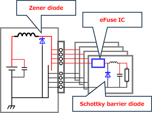
Also, negative voltage may be generated on the board side due to inductance on the board side. The magnitude of this negative voltage depends on the load current and inductance that were flowing just before the device turned off. In order to prevent this voltage from occurring, it is necessary to lower (shorten and thicken) the inductance of the power supply and GND lines controlled by the eFuse IC. Check with the actual device, and if the magnitude of negative voltage becomes a problem, take countermeasures by inserting a Schottky barrier diode (SBD).
(Fig. 4 shows an example of power line countermeasures for hot swap equipment)
Related Links
The following documents also contain related information:
FAQs
Application Notes
* Company names, product names, and service names used in this FAQ may be of their respective companies.