

- General Top
- SEMICONDUCTOR
- STORAGE
- COMPANY
-
My ToshibaSemicon
- Semiconductor Top
-
ApplicationsAutomotive
Body Electronics
xEV
In-Vehicle Infotainment
Advanced Driver-Assistance Systems (ADAS)
Chassis
IndustrialInfrastructure
BEMS/HEMS
Factory Automation
Commercial Equipment
Consumer/PersonalIoT Equipment
Healthcare
Wearable Device
Mobile
Computer Peripherals
-
ProductsAutomotive Devices
Discrete Semiconductor
Diodes
Transistors
Logic ICs
Analog Devices
Digital Devices
Wireless Devices
※
 : Products list (parametric search)Power Semiconductors
SiC Power Devices
※
: Products list (parametric search)Isolators/Solid State RelaysPhotocouplers
Digital Isolators
Solid State Relays
Fiber Optic Transmitting Modules
※
: Products list (parametric search)MOSFETsIGBTs/IEGTsBipolar Transistors※
: Products list (parametric search)Diodes※
: Products list (parametric search)MicrocontrollersMotor Driver ICsIntelligent Power ICs※
: Products list (parametric search)Power Management ICsLinear ICs※
: Products list (parametric search)General Purpose Logic ICsLinear Image SensorsOther Product ICsOther Product ICs
※
: Products list (parametric search) -
Design & Development
-
Knowledge
- Where To Buy



- Part Number & Keyword Search
- Cross Reference Search
- Parametric Search
- Stock Check & Purchase
This webpage doesn't work with Internet Explorer. Please use the latest version of Google Chrome, Microsoft Edge, Mozilla Firefox or Safari.
require 3 characters or more. Search for multiple part numbers fromhere.
The information presented in this cross reference is based on TOSHIBA's selection criteria and should be treated as a suggestion only. Please carefully review the latest versions of all relevant information on the TOSHIBA products, including without limitation data sheets and validate all operating parameters of the TOSHIBA products to ensure that the suggested TOSHIBA products are truly compatible with your design and application.Please note that this cross reference is based on TOSHIBA's estimate of compatibility with other manufacturers' products, based on other manufacturers' published data, at the time the data was collected.TOSHIBA is not responsible for any incorrect or incomplete information. Information is subject to change at any time without notice.
require 3 characters or more.
Model-Based Development (MBD) Technology to Resolve EMC Issues at the Early Design Stage
We have established a model-based development (MBD) technology that enables highly accurate prediction of EMI and EMS characteristics at the circuit design stage for automotive ICs.
This technology allows EMC-related issues—which have traditionally been identified in the later stages of development—to be resolved at an early design phase, significantly reducing the risk of redesign.
Market Background Driving the Need for MBD
The automotive industry is undergoing a major transformation. With ECU consolidation driven by zonal architectures, the risk of malfunction due to EMI affecting other ECUs, as well as EMS-induced failures within IC circuits, is increasing.
To ensure safety in autonomous driving systems, automotive semiconductor devices such as communication ICs are required to have strong EMC robustness. As a result, resistance to malfunction caused by EMI/EMS is becoming more critical than ever.
At the same time, there is an increasing demand for shorter development cycles, making simulation-based verification essential.
Against this backdrop, we are focusing on the development and provision of highly accurate models for automotive semiconductor devices, as well as the enhancement of MBD-based verification technologies.
In addition to electrical circuit simulation, these technologies support:
- Electro-mechanical coupled analysis incorporating actuator models
- Transient thermal analysis
- EMI/EMS analysis
EMI (Electromagnetic Interference) Simulation Technology
For EMI and EMS analysis, we developed a highly accurate model using an automotive communication IC (TB9032FNG).
During IC development, a trade-off arises: smoothing the driver output waveform to reduce EMI makes it difficult to meet AC characteristics defined by communication standards (ISO 20794).
By utilizing high-accuracy simulation, we optimized this trade-off.
Specifically, the following techniques were applied:
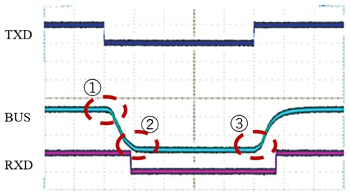
- Slew rate control for the rising and falling edges of the BUS waveform
- Edge rounding control (Figure 1. (1)–(3))
By smoothing sharp transitions in the BUS waveform, an improvement of 5–15dBµV in EMI characteristics (150Ω method) was achieved.
In addition, rounding control suppresses switching noise caused by undershoot (ground bounce) during transitions to the dominant (Low) state.
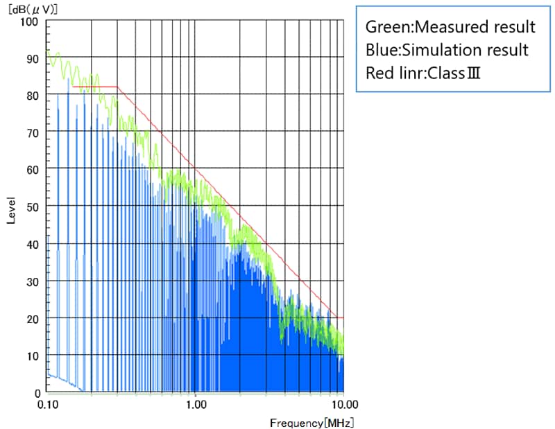
The impact of these measures on EMI characteristics can be evaluated at the circuit design stage through simulation. As shown in Figure 2 (Green line), noise spectrum reduction can be confirmed by BUS waveform control.
EMI (150Ω method) measurements were also conducted using actual TB9032FNG samples developed through this validation process.
Figure 2 compares measurement results with simulation results, demonstrating strong agreement and confirming the high predictive accuracy of the model.
This enables quantitative prediction of EMI reduction effects and allows optimization of noise mitigation at the design stage.
EMS (Electromagnetic Susceptibility) Simulation Technology
Simulation at the circuit design stage is also effective for EMS.
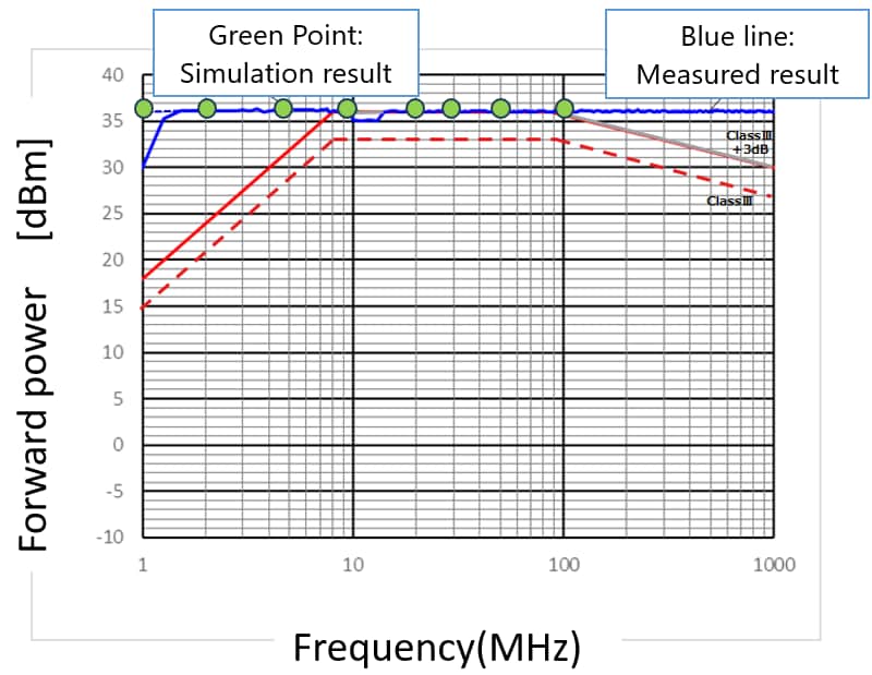
When external noise such as that used in the DPI (Direct Power Injection) method is applied during semiconductor evaluation, it can cause malfunction of internal semiconductor devices and circuits.
To prevent such issues, it is essential to verify IC robustness at the circuit design stage.
Verification is performed by analyzing:
- Sensitivity of parasitic transistors
- Spatial relationships between devices
and confirming the absence of issues through simulation.
As shown in Figure 3, a strong correlation between simulation and measurement results has also been confirmed for the DPI method.
Summary
Through the TB9032FNG case study, we confirmed strong correlation between simulation and measurement results for both EMI and EMS using MBD.
By utilizing highly accurate IC models, simulation can be extended to include surrounding passive components and printed circuit boards, enabling system-level verification.
In conventional automotive system development, EMC evaluation has typically been conducted in the later stages—after final components are available—often leading to redesign when issues are discovered.
Our approach significantly reduces this risk and enables shorter development cycles.
Going forward, we will continue to contribute to both enhanced reliability and reduced development time for automotive systems by providing semiconductor device models aligned with industry needs, and by delivering solutions suitable for next-generation architectures.
Related Link

* Company names, product names, and service names may be trademarks of their respective companies.