
- General Top
- SEMICONDUCTOR
- STORAGE
- COMPANY
-
My ToshibaSemicon
- Semiconductor Top
-
ApplicationsAutomotive
Body Electronics
xEV
In-Vehicle Infotainment
Advanced Driver-Assistance Systems (ADAS)
Chassis
IndustrialInfrastructure
BEMS/HEMS
Factory Automation
Commercial Equipment
Consumer/PersonalIoT Equipment
Healthcare
Wearable Device
Mobile
Computer Peripherals
-
ProductsAutomotive Devices
Discrete Semiconductor
Diodes
Transistors
Logic ICs
Analog Devices
Digital Devices
Wireless Devices
※
 : Products list (parametric search)Power Semiconductors
SiC Power Devices
※
: Products list (parametric search)Isolators/Solid State RelaysPhotocouplers
Digital Isolators
Solid State Relays
Fiber Optic Transmitting Modules
※
: Products list (parametric search)MOSFETsIGBTs/IEGTsBipolar Transistors※
: Products list (parametric search)Diodes※
: Products list (parametric search)MicrocontrollersMotor Driver ICsIntelligent Power ICs※
: Products list (parametric search)Power Management ICsLinear ICs※
: Products list (parametric search)General Purpose Logic ICsLinear Image SensorsOther Product ICsOther Product ICs
※
: Products list (parametric search) -
Design & Development
-
Knowledge
- Where To Buy


- Part Number & Keyword Search
- Cross Reference Search
- Parametric Search
- Stock Check & Purchase
This webpage doesn't work with Internet Explorer. Please use the latest version of Google Chrome, Microsoft Edge, Mozilla Firefox or Safari.
require 3 characters or more. Search for multiple part numbers fromhere.
The information presented in this cross reference is based on TOSHIBA's selection criteria and should be treated as a suggestion only. Please carefully review the latest versions of all relevant information on the TOSHIBA products, including without limitation data sheets and validate all operating parameters of the TOSHIBA products to ensure that the suggested TOSHIBA products are truly compatible with your design and application.Please note that this cross reference is based on TOSHIBA's estimate of compatibility with other manufacturers' products, based on other manufacturers' published data, at the time the data was collected.TOSHIBA is not responsible for any incorrect or incomplete information. Information is subject to change at any time without notice.
require 3 characters or more.
TLCS-900/H1 Series Development System
model 15 In-Circuit Emulation System
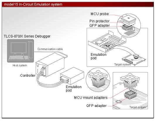
The model 15 In-Circuit Emulation System is comprised of the Integrated Development Environment, model 15 controller, model 15 emulation pod, and accessories.The model 15 In-Circuit Emulation System is a low-priced version of model 25 system with the less basic functions.
- Real-time PC/PD trace.
- Trace control using an event feature.
- Capable of referring to the memory during program execution.
| Host interface | Ethernet, RS-232C: 25 pin straight cable | |
|---|---|---|
| Emulation memory | 4 Mbytes | |
| Event | Number of points | 8 points |
| Comparison items | Address, data, status, external input | |
| Comparison conditionscondition | Match, unmatch, range | |
| Pass count | 1 to 256 times | |
| Event trigger actions | Break, trace control, timer control, external trigger output | |
| Event combinations | AND, OR, sequential | |
| Hardware break | 4 points | |
| Software break | 1024 points | |
| Trace memory Capacity | 8192 frames (Note) | |
| Trace memory Modes | Free trace, trigger trace, overwriting prohibit, sampling trace, overflow stop | |
| Trace items | PC address, data address, data value, status, external output, external input, tag timer, event | |
| Timer measurement | Run timer: 1 channel, Lap timer: 1 channel | |
| Memory access | Memory display during program execution | 128 bytes |
| Memory rewrite during program execution | - | |
| Program variables | Display | Binary, octal, decimal or hexadecimal display can be selected for each variable. |
| Registration | Variables, arrays, structures and unions can be registered by the elements. | |
| Sauce display | - Source - Source + assembler code - Source + assembler code + machine language |
|
| External output | 1 line | |
| External input | 1 line | |
| Performance analysis: Module time measurement | - | |
| Performance analysis: Coverage measurement | - | |
| Flash programming/security feature | - | |
(Note) The trace memory capacity may vary depending on the trace conditions and operating states.
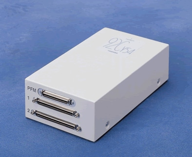
RTE900/H1 model 15 In-Circuit Emulator
Emulation pod for TLCS-900/H1 series; product structure and surface appearance

Standard contents of the product package
- Emulation pod
- MCU probe
- QFP adapter
- External I/O probe
- FG cable
- User's manual
| Emulation pod | Operating frequency and voltage for emulation | Remarks |
|---|---|---|
| BM92C820F0A-M15 | 4MHz - 40MHz@3.0V - 3.6V 30kHz - 34kHz@3.0V - 3.6V |
- |
| BM92CH21F0A-M15 | 6MHz - 40MHz@3.0V - 3.6V 30kHz - 34kHz@3.0V - 3.6V |
- |
| BM92CM22F0A-M15 | 4MHz - 40MHz@3.0V - 3.6V | - |
| BM92CY23F0A-M15 | 6MHz - 40MHz@3.0V - 3.6V 30kHz - 34kHz@3.0V - 3.6V |
|
| BM92FD23AF0A-M15 | 6MHz - 10MHz@3.0V - 3.6V 30kHz - 34kHz@3.0V - 3.6V |
- |
| BM92CA25F0A-M15 | 6MHz - 40MHz@3.0V - 3.6V 30kHz - 34kHz@3.0V - 3.6V |
- |
| BM92CM27F0A-M15 | 4MHz - 40MHz@3.0V - 3.6V | - |
| BM92CD28F0A-GM | 8MHz - 10MHz@3.0V - 3.6V 30kHz - 34kHz@3.0V - 3.6V |
- |
| BM92CY54F0A-M15 |
8MHz - 10MHz@4.75V - 5.25V 30kHz - 34kHz@4.75V - 5.25V |
- |
Concerning emulation operating frequency and voltage
- Electric power for the target system cannot be supplied to the emulator. The power source for the emulation must be the one in the emulation pod. The emulation pod cannot supply electric power to the target system.
- The operating voltage cannot be changed during the emulation operation.
- The power source voltage of the emulation is 5V +/- 5%.
- For operating the emulation, the oscillator mounted on the emulation pod is used. The oscillator mounted on the target system cannot be used. Please refer to the emulation pod's user manual for how to change the oscillator mounted on the emulation pod.
- The low frequency (SLOW) emulation operating frequency is fixed at 32.768kHz.
RTE model 15
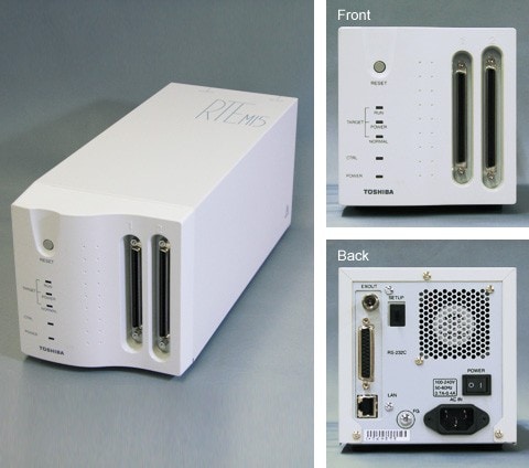
RTE Controller model 15 is a control unit to set up RTE model 15 system. Using RTE Controller model 15 together with an emulation pod and a debugger, enables sophisticated debugging.
Contents of the product package
- RTE Controller model 15
- Emulation pod Connection cable 1
- Emulation pod Connection cable 2
- Power cable
- The Integrated Development Environment (IDE):1 download license (from website) (Note)
- User's manual
(Note) The Integrated Development Environment does not support TLCS-870/X Series. For the TLCS-870/X Series, purchase theTLCS-870/X Series Debugger.
| Power supply | AC100V - 240V |
|---|---|
| Power supply frequency |
50Hz - 60Hz |
| External Dimensions | 136(H)*130(W)*320(D)mm |
| Weight | approx. 2.7kg |
Accessories
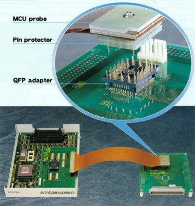
MCU probes
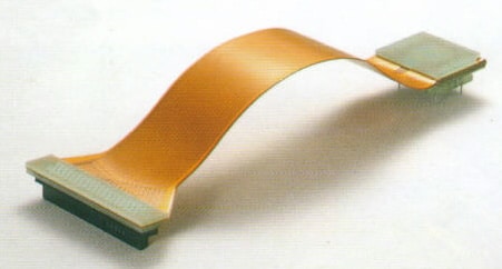
The MCU probe connects the emulation pod to a target system designed for the corresponding MUC which in a QFP package. The probe is designed to fit any QFP.
Contents of the package accommodating QFP package
| MCU probe | 1 |
|---|---|
| Pin protector | 1 |
| QFP adapter | 1 |
| Manual | 1 |
Contents of the package accommodating DIP package
| MCU probe | 1 |
|---|---|
| Manual | 1 |
External dimensions of QFP probes
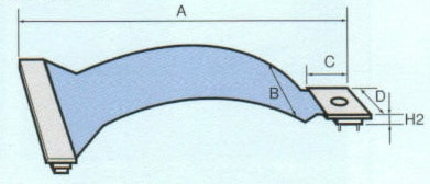
| MCU probe | IC Package (body size and pich) |
A |
B | C | D | H2 |
|---|---|---|---|---|---|---|
| PN100002 | DIP42 | 526.2 | 53.3 | 19.0 | 56.5 | 5.0 |
| PN100003 | DIP28 | 536.0 | 35.5 | 19.0 | 37.5 | 18.5 |
| PN100004 | DIP20 | 525.0 | 25.5 | 12.5 | 27.5 | 9.0 |
| PN110001 | SDIP64 | 176.0 |
57.0 | 23.0 | 60.0 |
- |
| PN110003 | SDIP42 | 538.0 | 53.0 | 19.0 |
37.5 | 18.0 |
| PN110005 | SDIP64 | 329.0 | 52.0 |
23.0 | 59.0 | 10.0 |
| PN110006 | SDIP64 | 522.5 |
57.0 | 22.5 | 59.0 | 9.0 |
| PN110007 | SDIP64 | 160.0 | 43.0 | 40.0 |
60.0 | 15.0 |
| PN110008 | SDIP64 | 350.0 | 50.5 | 44.0 | 60.0 |
48.0 |
| PN110009 | SDIP64 | 332.5 | 50.5 |
26.5 | 60.0 | 48.0 |
| PN120001 | QFP100, 22x22, 0.80 | 332.0 | 40.0 |
34.0 | 34.0 | 34.0 |
| PN120004 | QFP80, 14x20, 0.80 | 340.0 | 40.0 |
27.0 | 35.0 | 12.5 |
| PN120005 | QFP100, 14x20, 0.65 | 286.0 |
50.0 | 26.0 |
35.0 | 12.5 |
| PN120006A | QFP80. 12x12, 0.50 | 291.5 | 40.0 | 26.0 | 26.0 | 13.5 |
| PN120009 | QFP80. 14x20, 0.80 | 200.0 | 40.0 |
27.0 | 30.0 | 12.5 |
| PN120010 | QFP100, 22x22, 0.80 | 294.0 |
56.0 | 35.0 | 35.0 |
12.5 |
| PN120011 | QFP44, 10x10. 0.80 | 300.0 | 30.0 |
23.0 | 23.0 | 12.5 |
| PN120012 | QFP80, 14x14, 0.65 | 300.0 |
45.0 | 28.0 | 28.0 | 12.5 |
| PN120013 | QFP100, 14x14, 0.50 | 203.5 | 55.0 | 30.0 | 30.0 | 12.5 |
| PN120014 | QFP64, 14x20, 1.00 | 336.0 | 37.0 | 32.0 | 25.0 | 12.5 |
| PN120016 | PLCC84 | 295.0 | 46.0 | 46.0 | 35.0 | 9.0 |
| PN120017 | QFP100, 22x22, 0.80 | 126.0 | 60.0 | 53.0 | 44.0 | 34.5 |
| PN120019 | QFP44, 14x14, 0.80 | 267.0 | 33.0 | 31.0 | 45.0 |
39.5 |
| PN120020 | QFP64, 14x20, 1.00 | 267.0 | 33.0 | 30.0 | 60.0 | 39.5 |
| PN120022 | QFP64, 10x10, 0.50 | 337.0 | 37.0 | 32.0 | 32.0 | 13.5 |
| PN120023B | QFP100, 14x20, 0.65 | 310.0 |
26.0 |
50.0 | 44.0 | 10.0 |
| PN120025 | QFP100, 14x14, 0.50 | 309.0 | 35.0 | 56.0 |
44.0 | 19.5 |
| PN120027 | QFP144, 20x20, 0.50 | 200.0 | 55.6 |
35.0 | 38.4 | 14.5 |
| PN120030 | QFP44, 10x10, 0.80 | 430.0 | 33.5 | 30.0 | 48.0 | 35.5 |
| PN120032 | QFP120, 28x28, 0.80 | 255.0 | - | 50.0 | 50.0 | 15.0 |
| PN120036 | QFP100, 22x22, 0.80 | 200.0 | 42.0 | 35.0 |
36.0 | 12.5 |
| PN120038A | QFP80, 14x20, 0.80 | 408.0 | 40.0 | 40.0 | 40.0 | 22.0 |
| PN120039A | QFP64, 14x14, 0.80 | 150.0 |
31.0 | 31.0 | 31.0 | 12.5 |
| PN120040A | QFP160, 28x28, 0.65 | 150.0 | 60.0 | 45.0 | 45.0 | 15.0 |
| PN120042 | QFP80, 12x12, 0.50 | 200.0 | 34.0 | 33.0 | 34.0 | 12.5 |
| PN120044 | QFP144, 16x16, 0.40 | 200.0 | 55.6 | 35.0 | 38.4 | 12.5 |
| PN120050 | QFP144, 20x20, 0.50 | 150.0 | 60.0 |
45.0 | 45.0 | 15.0 |
| PN120052 | QFP64, 14x14, 0.80 | 359.5 | 38.0 | 38.0 | 38.0 | 13.5 |
| PN120053 | QFP120, 14x14, 0.40 | 200.0 | 50.0 | 35.0 |
35.0 |
12.5 |
| PN120057 | QFP128, 14x14, 0.40 | 200.0 | 47.6 | 33.0 | 33.0 | 12.5 |
| PN190001 | QFP40, 64, DIP40.SDIP64 | 52.5 | 57.5 | 10.5 | 78.0 | 9.0 |
| PN190002 | QFP80, 80-pin header | 40.0 | 50.0 | 10.0 | 78.0 | 19.0 |
QFP adapters
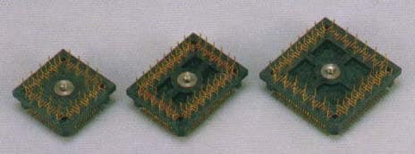
The QFP adapter is used to connect an emulation pod to the target system. Because the leads of the QFP adaptor are designed for versatility, their footprints are a little different from those of the actual MCU and OTP. If there is a need to install both the adapter and the device, the board footprint must be designed to provide compatibility with both of them.
(The QFP adapters have the identical specifications with the products made by TOKYO ELETECH CORPORATION. For correspondence between the product numbers of QFP adapters and those of TOKYO ELETECH's products, and the recommended foot patterns, see TOKYO ELETECH CORPORATION's web site.)
Pin protector
The pin protector protects the pins which connect the MCU probe and the QFP adapter. If the MCU probe is repeatedly connected without the pin protector, rhe connection will eventually loosen. Thus Toshiba recommend changing the pin protector after every 100 unpluggings.
MCU mount adapters

Using the MCU mount adapter and the QFP adapter together allows you to mount the MCU on the target system.
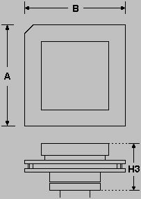
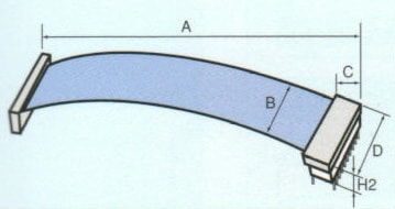
External Dimensions
| MCU mount adapter | IC Package (body size pitch) |
A | B | H3 |
|---|---|---|---|---|
| PN210002 | QFP80, 14x20, 0.80 | 40.0 | 45.0 | 27.0 |
| PN210005A | QFP100, 14x20, 0.65 | 26.6 | 32.2 |
19.0 |
| PN210008 | QFP80, 12x12, 0.50 | 33.02 | 33.02 | 25.3 |
| PN210011A | QFP64, 14x20, 1.00 | 29.0 | 36.0 |
20.0 |
| PN210013A | QFP100, 22x22, 0.80 | 39.0 |
39.0 | 22.0 |
| PN210018 | QFP80, 14x14, 0.65 | 26.0 | 26.0 | 17.0 |
| PN210020A | QFP44, 10x10, 0.80 | 26.0 | 26.0 | 25.0 |
| PN210023 | QFP100, 14x14, 0.50 | 37.5 | 37.5 | 24.0 |
| PN210026 | QFP64, 14x14, 0.80 | 26.0 | 33.0 | 17.0 |
| PN210030 | QFP160, 28x28, 0.65 |
50.0 | 50.0 | 23.0 |
| PN210033 | QFP64, 10x10, 0.50 | 44.0 | 46.0 | 32.0 |
| PN210036 | QFP144, 20x20, 0.50 | 60.0 | 60.0 | 24.5 |
| PN210044 | QFP144, 16x16, 0.40 | 25.0 | 25.0 | 7.4 |
| PN210051 | QFP120, 14x14, 0.40 |
23.0 | 23.0 | 7.4 |
| PN210054 | QFP128, 14x14, 0.40 | 23.0 | 23.0 | 7.4 |