


TLCS-870/C1 Series Development System
On-Chip Debug Emulation System
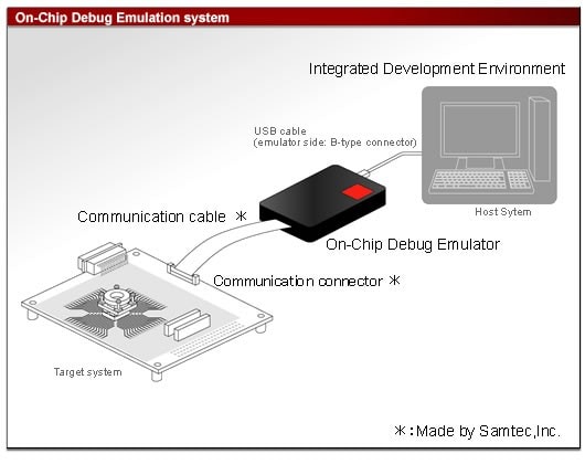
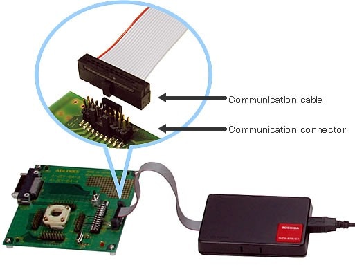
The RTE870/C1 On-Chip Debug Emulation System consists of Integrated Development Environment and a communication cable (Note). It provides various debug functions by controlling the on-chip debug function of the microcomputer mounted onto the target system.
(Note) Made by Samtec,Inc.
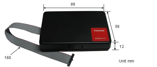
- Business-card-sized compact emulator
- No need for power supply (using USB bus power)
- Communicates with a MCU via two terminals.
- No user ROM/RAM area occupied by the emulator.
- IDE included (downloadable from website)
Check the product names and numbers at this website
The product information is also provided in "Comprehensive List (Microcomputers)" under "Document" for your use.
| Host interface | USB2.0 Full-speed | |
|---|---|---|
| Emulation memory | internal FLASH ROM | |
| Event | Number of points | 1 points (Notes-1) |
| Comparison items | Address, data, status | |
| Comparison conditionscondition | Match, mask | |
| Pass count | 1 time | |
| Event trigger actions | Break | |
| Event combinations | - | |
| Hardware break | 9 points (Notes-2) | |
| Software break | - | |
| Trace memory Capacity | Last two branches (program execution main mode) Last 8000 branches (trace storage main mode) |
|
| Trace memory Modes | Program execution main, trace storage main | |
| Trace items | PC address | |
| Timer measurement | - | |
| Memory access | Memory display during program execution | At fixed intervals: 32 bytes (Notes-3) |
| Memory rewrite during program execution | 1 address(1 byte) (Notes-3) | |
| Program variables | Display | Binary, octal, decimal or hexadecimal display can be selected for each variable. |
| Registration | Variables, arrays, structures and unions can be registered by the elements. | |
| Sauce display | - Source - Source + assembler code - Source + assembler code + machine language |
|
| External output | - | |
| External input | - | |
| Performance analysis: Module time measurement | - | |
| Performance analysis: Coverage measurement | - | |
| Flash programming/security feature | It is possible to write program to the internal FLASH ROM on debugging phase. | |
(Notes-1) Shared with Hardware break
(Notes-2) 1 point shared with event
(Notes-3) Wait of 1 clock cycle per write of 1 byte
Memory Access
- "Running data display feature" (IDE feature name "Watch")
Capable of displaying the values of registered variables. The registered variable value display is updated when the target program is stopped, but it is also possible to set to update at constant intervals during program execution.
(Note) Wait of 1 clock cycle per write of 1 byte. - "Running data rewrite feature" (IDE feature name "Tuning")
Capable of freely changing the contents of the memory without requiring a user to stop a program while running it. Changeable areas include MCU's I/O area and built-in RAM area. This allows you to adjust program operation by every parameter value change.
(Note) Wait of 1 clock cycle per write of 1 byte.
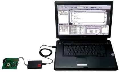
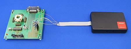
Product Configuration and Appearance of On-Chip Debug Emulation System
Content of Product
- RTE870/C1 On-Chip Debug Emulator main body
- Communication cable (already connected to the emulator main body) (Notes)
- Communication connector (Notes)
- One license for downloading the Integrated Development Environment from website.
(Notes) Made by Samtec,Inc.
Items to Be Prepared by Customer
- Host system
- USB cable (emulator side: B-type connector)
- Microcomputer on the target system (with on-chip debug function incorporated)
The on-chip debug function uses two pins for communications (OCDCK, OCDIO) and four pins for monitor signals (VDD, GND, RESET, MODE). When the On-Chip Debug Emulator is connected to the target system, the OCDCK and OCDIO pins are used exclusively by the Emulator and cannot be used as port pins (P20, P21) or UART0/SIO0 pins.
For the operation assurance range and characteristics of the supplied power/clock, see the microcomputer's datasheet.
About Connection to Target System
Seeing the following pin assignment table, etc., lay out/mount the Communication Connector (FTSH series 20pin connector made by Samtec, Inc.) on to the target system where the RTE870/C1 on-chip debug emulation system (BMP89A400010A-G or OCDE mode of BMP89A300010A-G) is to be connected.
One Communication Connector comes with an emulator, but those of the identical series (FTSH series) released from Samtec, Inc. are also available.
FTSH-110-01-[*]-[*][*]-[*][*]
[*] of the part number indicates a connector option. When purchasing, choose a suitable option according to its usage. For details specifications, please visit Samtec, Inc. website.
Communication Connector attached to an Emulator
| Part Nnumber | Note |
|---|---|
| FTSH-110-01-L-DV-K |
Surface mount type with keying shroud |
Communication Connector Pin Assignment Table
| Connector Pin No. |
Signal Name |
|---|---|
| 1 | GND(VSS) |
| 3 | MODE |
| 5 | GND(VSS) |
| 7 | VDD |
| 9 | GND(VSS) |
| 11 | /RESET |
| 13 | GND(VSS) |
| 15 | OCDCK |
| 17 | GND(VSS) |
| 19 | OCDIO |
| Connector Pin No. |
Signal Name |
|---|---|
| 2 | GND(VSS) |
| 4 | GND(VSS) |
| 6 | GND(VSS) |
| 8 | VDD |
| 10 | GND(VSS) |
| 12 | GND(VSS) |
| 14 | GND(VSS) |
| 16 | GND(VSS) |
| 18 | GND(VSS) |
| 20 | GND(VSS) |
(Notes) For the MCU pin numbers, signal names and connection method, be sure to see a data sheet for the target MCU.
(Notes) Minimize on-board wiring between the Communication Connector and MCU. (Shortest wiring recommended)
(Notes) A VDD to be connected to the emulator is for monitoring. The power cannot be supplied from the emulator to the target system.
(Notes) If a control circuit or other part is connected to a signal (OCDCK, OCDIO) connected to the emulator on the target system, separate them with a jumper, etc. because they may affect control of the emulator.
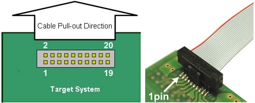
Note for Layout of Communication Cable Connector
The following figure shows the cable pull-out direction and connector pin position, when the emulator is connected. To design the board, take into account interference with other parts at the time of connecting the communication cable. For a connector size, please visit Samtec, Inc. website.
About Emulation Operating Voltage/Frequency
- To use all the on-chip debug functions offered by this Emulator, the target system must be operating within the target MCU's guaranteed operating voltage range for FLASH program and erase operations. The load (FLASH program) function using this Emulator cannot be guaranteed outside this voltage range.
For the guaranteed operating voltage range for FLASH program and erase operations, see the microcomputer’s datasheet. - If the Emulator is to be used outside the guaranteed FLASH program/erase operating voltage range and the MCU's guaranteed operating voltage range, the FLASH memory must be programmed with a programming tool prior to using the Emulator.
- Any operating frequency in the device operation assurance range is available.
- Note that the power/clock cannot be supplied from the emulator to the target system.
Precautions for USB Connection
- The emulator is connected to the host system via the USB. (USB2.0 Full-speed)
- To newly connect the emulator to the host system, it is necessary to install a USB driver.
- Depending on the USB's destination (host system), a protocol error may occur on rare occasions. If this error occurs, replace the USB connection cable with the following.
Recommended cable: 0.7 m or longer USB cable with ferrite cores attached to its both ends
Accessory
Communication Cable
The communication cable is used to connect the emulator or the FLASH Writer to the target system. It is pre-plugged to the emulator or the FLASH Writer.
The communication cable is available from Samtec, Inc. For detailed specifications, please visit Samtec, Inc. website.
The recommended product can also be purchased from the following agencies.
| Name | Part Number | Remark |
|---|---|---|
| Communication cable | FFSD-10-D-07.00-01-N |
Pre-plugged to the emulator or the FLASH Writer |
Communication Connector
The communication connector is used to connect the emulator to the target system. The part numbers shown below are examples. Other mount types, such as through-hole, and other mating options are also available to meet the specific needs of each customer.
The communication connector is available from Samtec, Inc. For detailed specifications, please visit Samtec, Inc. website.
The recommended product can also be purchased from the following agencies.
| Name | Part Number |
Remark |
|---|---|---|
| Communication connector | FTSH-110-01-L-DV-K | Surface mount type with keying shroud (Recommended) Each emulator comes with one communication connector. |
Option Tools / Option Parts
Various option tools and option parts are available from third parties for efficient project development. Find products that meet your specific application needs. For the specifications and order information on these products, please contact each third party directly.
Simple EV Board
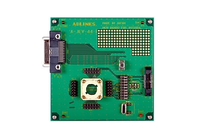
The simple EV board is an evaluation board for the TLCS-870/C1 Series of microcontrollers with the on-chip debug function. This board is useful for performing simple evaluation when the actual target system cannot be used. In addition to on-chip debug emulation, the simple EV board also supports in-circuit emulation by using a probe from ADLINKS Corporation (Note).
The simple EV board is available from ADLINKS Corporation. For details, please visit ADLINKS Corporation website.
(Note) In-circuit emulation does not allow the emulation of the signal lines (OCDCK, OCDIO) that are used for debug communications between the emulator and target microcontroller.
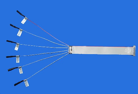
Test Clip Communication Cable
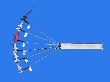
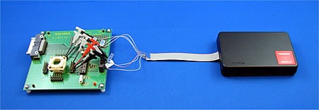
The test clip communication cable is a connecting cable that connects to a target system with test clips. This cable enables the emulator to be connected to a target system without mounting a dedicated connector on the target system.
The test clip communication cable is available from ADLINKS Corporation. For product specifications, please visit ADLINKS Corporation website.
Socket Type Communication Cable
The socket type communication cable is a connecting cable that connects to a target system with sockets. This cable enables the emulator to be connected to a target system without mounting a dedicated connector on the target system.
The socket type communication cable is available from ADLINKS Corporation. For product specifications, please visit ADLINKS Corporation website.