
- General Top
- SEMICONDUCTOR
- STORAGE
- COMPANY
-
My ToshibaSemicon
- Semiconductor Top
-
ApplicationsAutomotive
Body Electronics
xEV
In-Vehicle Infotainment
Advanced Driver-Assistance Systems (ADAS)
Chassis
IndustrialInfrastructure
BEMS/HEMS
Factory Automation
Commercial Equipment
Consumer/PersonalIoT Equipment
Healthcare
Wearable Device
Mobile
Computer Peripherals
-
ProductsAutomotive Devices
Discrete Semiconductor
Diodes
Transistors
Logic ICs
Analog Devices
- Automotive SmartMCD™ (Integreted SoC Conbining Microcontroller and Driver)
- Automotive Brushless Motor Driver ICs
- Automotive Brushed DC Motor Driver ICs
- Automotive Stepping Motor Driver ICs
- Automotive Driver ICs
- Automotive System Power Supplies ICs
- Automotive audio power amplifier ICs
- Automotive Network Communication
Digital Devices
Wireless Devices
※
 : Products list (parametric search)Power Semiconductors
SiC Power Devices
※
: Products list (parametric search)Isolators/Solid State RelaysPhotocouplers
Digital Isolators
Solid State Relays
Fiber Optic Transmitting Modules
※
: Products list (parametric search)MOSFETsIGBTs/IEGTsBipolar Transistors※
: Products list (parametric search)Diodes※
: Products list (parametric search)MicrocontrollersMotor Driver ICsIntelligent Power ICs※
: Products list (parametric search)Power Management ICsLinear ICs※
: Products list (parametric search)General Purpose Logic ICsLinear Image SensorsOther Product ICsOther Product ICs
※
: Products list (parametric search) -
Design & Development
-
Knowledge
- Where To Buy


- Part Number & Keyword Search
- Cross Reference Search
- Parametric Search
- Stock Check & Purchase
This webpage doesn't work with Internet Explorer. Please use the latest version of Google Chrome, Microsoft Edge, Mozilla Firefox or Safari.
require 3 characters or more. Search for multiple part numbers fromhere.
The information presented in this cross reference is based on TOSHIBA's selection criteria and should be treated as a suggestion only. Please carefully review the latest versions of all relevant information on the TOSHIBA products, including without limitation data sheets and validate all operating parameters of the TOSHIBA products to ensure that the suggested TOSHIBA products are truly compatible with your design and application.Please note that this cross reference is based on TOSHIBA's estimate of compatibility with other manufacturers' products, based on other manufacturers' published data, at the time the data was collected.TOSHIBA is not responsible for any incorrect or incomplete information. Information is subject to change at any time without notice.
require 3 characters or more.
Isolators/Solid State Relays / Junction FETs Part Naming Conventions
Clicking on product's category allows you to see Isolators/Solid State Relays Part Naming Conventions.
Photocouplers
3-Digit Part Numbering Example (Except Alphabetical Characters)

1. TLP means photocoupler.
2. The first digit indicates the package type as shown below.
| Number | Package and Breakdown voltage |
|---|---|
| 1 | SOP |
| 2 | SOP / SOP16 / DIP (2500 Vrms/5000 Vrms) |
| 3 | DIP (5000 Vrms) |
| 4 | DIP4 (5000 Vrms) |
| 5 | DIP (2500 Vrms) |
| 6 | DIP (5000 Vrms) |
| 7 | DIP (4000 Vrms) |
3. Output style
This section expresses output style.
- 00 to 09: IC output, Photorelay
- 10 to 19: IC output
- 20 to 29: 4/8/16-pin multi-channel photocoupler
- 30 to 39: 6 pin
- 40 to 49: Thyristor output, Photorelay
- 50 to 59: IC output
- 60 to 69: Triac output
- 70 to 79: Photorelay
- 80 to 89: Transistor output / Darlington Transistor output
- 90 to 99: Transistor output, Photorelay, Photo voltaic output
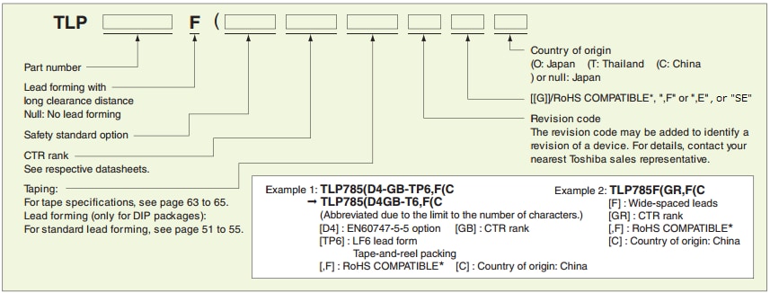
4. Suffix
Withstand voltage level, etc.
Details are as follows.
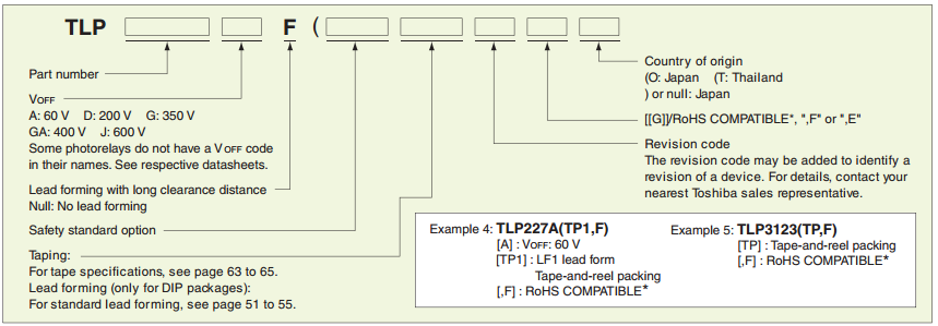
(a) Photorelay
- A: 40 V, 60 V
- D: 200 V
- G: 350 V
- GA: 400 V
- J: 600 V
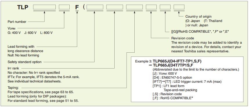
(b) Triac output, Thyristor output
- G: 400 V
- J: 600 V
- L: 800 V
(Note 1)
All of our photocouplers comply with UL standards. And as for standards other than UL, the situations are different between each product. For details, see the Toshiba product catalog or other appropriate document.
(Note 2)
For those parts which do not follow the numbering scheme shown above, see the appropriate datasheet or contact us using the Inquiry Sheet.
4-Digit Part Numbering Example (Except Alphabetical Characters)

1. TLP means photocoupler.
2. The first digit indicates the product category as shown below.
| Number | Product Category |
|---|---|
| 2 | IC output (logic, IPM drivers) |
| 3 | Photorelay (1-form-A) / Triac output / Photo voltaic output |
| 4 | Photorelay (except 1-form-A) |
| 5 | IC output (Power device driver) |
3. If the first digit is 3 or 4, the second digit indicates the subcategory as shown below.
| Number | Product Category, etc. |
|---|---|
| 0 | Triac output (Standard type) |
| 1 | Photorelay SOP |
| 2 | Photorelay SSOP |
| 3 | Photorelay USOP |
| 4 | Photorelay VSON |
| 5 | Photorelay DIP |
| 7 |
Triac output (High noise immunity) |
| 9 | Photo voltaic output |
If the first digit is 2, 5 or 7, the second digit indicates the package type as shown below.
| Number | Package |
|---|---|
| 0 | SO4 / MFSOP6 |
| 1 | SO8 (Dual ch.) |
| 2 | ― |
| 3 | SO6 package |
| 4 | SO8 (Single ch.) |
| 6 | DIP8 (Dual ch.) |
| 7 |
SDIP6 |
| 8 | ― |
| 9 | DIP8 (Single ch.) |
4. Part Number
(a) If the second digit of a triac-output photocoupler is 0 or 7, the next two digits indicates the following.
- 30 to 39: Breakdown voltage: 400 V, NZC
- 40 to 49: Breakdown voltage: 400 V, ZC
- 50 to 59: Breakdown voltage: 600 V, NZC
- 60 to 69: Breakdown voltage: 600 V, ZC
- 70 to 79: Breakdown voltage: 800 V, NZC
- 80 to 89: Breakdown voltage: 800 V, ZC
(b) If the second digit of a photorelay* is 1 to 4, the next two digits indicates the following.
- 00 to 09: High-current type
- 10 to 39: Standard type
- 40 to 69: Low-COFFtype
* If the second digit of a photorelay is 5, the next two digits indicates the following.
(c) If the second digit of a photovoltaic-output photocoupler is 9, the next two digits indicates the following.
- 00 to 19: Standard/economy type
- 20 to 29: High-VOC type
(Note 1)
All of our photocouplers comply with UL standards. And as for standards other than UL, the situations are different between each product. For details, see the Toshiba product catalog or other appropriate document.
(Note 2)
For those parts which do not follow the numbering scheme shown above, see the appropriate datasheet or contact us using the Inquiry Sheet.
Option Code Example
Standard Digital Isolators

1. DC means digital isolators.
2. Product Category
| Symbol | Product Category |
|---|---|
| L | Logic output |
| M | Logic output - Automotive |
3. Data Rate
| No. | Data rate(Mbps) |
|---|---|
| 1 | up to 1 |
| 2 | up to 10 |
| 3 | up to 50 |
| 4 | up to 100 |
| 5 | up to 200 |
Note) If the maximum data rate of the product is 150Mbps, this item will be 5.
Just because this item is 5 does not mean that the maximum data rate of the product is 200Mbps.
4. Total number of Channels (Forward direction, Reverse direction total)
5. Number of reverse channels
6. Control terminal, Default output state
| Symbol | Control terminal, Default output state |
|---|---|
| L | Output enable , Default output="L" |
| H | Output enable , Default output="H" |
| A | Input disable , Default output="L" |
| B | Input disable , Default output="H" |
| C | No control terminal , Default output="L" |
| D | No control terminal , Default output="H" |
7. Option
0: without option
8. Package
| Symbol | Package |
|---|---|
| 0 | SOIC8-N |
| 1 | SOIC16-W |
| 2 | SOIC8-DW |
| B | SSOP16 |
Additional Codes

1. Part number
2. Separators symbol
The left parenthesis separates a part number and the following additional codes.
3. packaging classification
e.g.) T: Taping
4. RoHS Compatible ( * )
e.g.) ,E: Compliant with European RoHS and halogen-free
* Please contact your Toshiba sales representative for details of RoHS compliance of each product.
5. Country of origin
e.g.) (O: Manufactured in Japan
e.g.) (T: Manufactured in Thailand
Note: There is a limit to the number of characters. For longer order numbers, the hyphen and comma characters may be omitted or additional codes may be abbreviated.
Fiber-Coupler (TOSLINK™)

1. Kind of module
This section shows the kind of module.
Products are classified into three kinds by their characteristics.
- TOTX : Optical Transmitting Module
- TORX : Optical Receiving Module
- TODX : Optical Transceiving Module
2. Directivity
This section shows the directivity of a product.
- 1 : Simplex Type
- 2 : Duplex Type
3. Internal structures of TOSLINK devices
This section shows the molding type of a product.
- 7 : Molded resin package (the maximum operation temperature : 70°C)
- 8 : ceramic package
- 9 : Molded resin package (the maximum operation temperature : 85°C)
4. Additional Number
5. Additional Number