
- General Top
- SEMICONDUCTOR
- STORAGE
- COMPANY
-
My ToshibaSemicon
- Semiconductor Top
-
ApplicationsAutomotive
Body Electronics
xEV
In-Vehicle Infotainment
Advanced Driver-Assistance Systems (ADAS)
Chassis
IndustrialInfrastructure
BEMS/HEMS
Factory Automation
Commercial Equipment
Consumer/PersonalIoT Equipment
Healthcare
Wearable Device
Mobile
Computer Peripherals
-
ProductsAutomotive Devices
Discrete Semiconductor
Diodes
Transistors
Logic ICs
Analog Devices
- Automotive SmartMCD™ (Integreted SoC Conbining Microcontroller and Driver)
- Automotive Brushless Motor Driver ICs
- Automotive Brushed DC Motor Driver ICs
- Automotive Stepping Motor Driver ICs
- Automotive Driver ICs
- Automotive System Power Supplies ICs
- Automotive audio power amplifier ICs
- Automotive Network Communication
Digital Devices
Wireless Devices
※
 : Products list (parametric search)Power Semiconductors
SiC Power Devices
※
: Products list (parametric search)Isolators/Solid State RelaysPhotocouplers
Digital Isolators
Solid State Relays
Fiber Optic Transmitting Modules
※
: Products list (parametric search)MOSFETsIGBTs/IEGTsBipolar Transistors※
: Products list (parametric search)Diodes※
: Products list (parametric search)MicrocontrollersMotor Driver ICsIntelligent Power ICs※
: Products list (parametric search)Power Management ICsLinear ICs※
: Products list (parametric search)General Purpose Logic ICsLinear Image SensorsOther Product ICsOther Product ICs
※
: Products list (parametric search) -
Design & Development
-
Knowledge
- Where To Buy


- Part Number & Keyword Search
- Cross Reference Search
- Parametric Search
- Stock Check & Purchase
This webpage doesn't work with Internet Explorer. Please use the latest version of Google Chrome, Microsoft Edge, Mozilla Firefox or Safari.
require 3 characters or more. Search for multiple part numbers fromhere.
The information presented in this cross reference is based on TOSHIBA's selection criteria and should be treated as a suggestion only. Please carefully review the latest versions of all relevant information on the TOSHIBA products, including without limitation data sheets and validate all operating parameters of the TOSHIBA products to ensure that the suggested TOSHIBA products are truly compatible with your design and application.Please note that this cross reference is based on TOSHIBA's estimate of compatibility with other manufacturers' products, based on other manufacturers' published data, at the time the data was collected.TOSHIBA is not responsible for any incorrect or incomplete information. Information is subject to change at any time without notice.
require 3 characters or more.
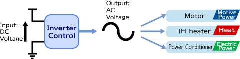
Inverter control
Recently it becomes common technology to use a microcontroller to do Inverter Control as a main controller. Toshiba has produced microcontrollers especially for the Inverter Control usage and expands strategically the lineup of the products to satisfy customers’ strong demand. The purpose of this document is to introduce the Inverter Control technology for non-professional engineers to easily understand the brief knowledge of the technology.
Inverter control
What is Inverter Control?
The primitive definition of “Inverter Control” is conversion from DC (Direct Current) to AC (Alternate Current). As known well, DC is the current whose voltage has a time-independent constant value, while AC voltage has time dependency. One of the most popular example of DC is the output voltage of a dry cell battery, and, AC, 60 Hz power supply which is available at home.
The Inverter Control is widely used in several kinds of energy conversion, for example, a motor control (electric energy to motive power) for an air conditioning system or washing machines, and so on, IH cooking machines (electricity to heat), and power conditioners which convert solar-generated electric power to home AC power supply (electric to electric).
How is the Inverter Control achieved?
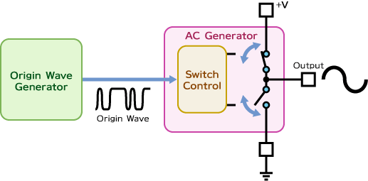
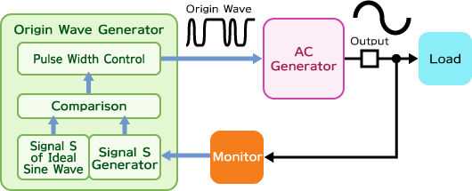
The system of the Inverter Control consists of two function circuitries. One of them is “Origin Wave Generator” for AC voltage, and the other is “AC generator” which produces a target AC voltage wave. The Origin Wave Generator makes a series of pulses whose heights are identical but widths are selected by the generator; the series of the pulses is “Origin Wave” for the target AC wave. The width of each pulse is decided by a special calculation which will be illustrated later.
And the AC generator modifies the Origin Wave to the AC wave. This circuit has several pairs of switches inside. For simple explanation, consider the case in which only one pair of two switches is existing in the function circuit. One of the terminals of one switch is tied to DC voltage source (V+) and the other switch, Ground level. Other terminals of both switches are connected each other, which makes output terminal of the AC Generator. Each switch is controlled by modification waves of the Origin Wave. This configuration can produce three voltage levels as the DC voltage level (V+), Ground level, and an intermediate level between V+ and Ground.
This explanation is dedicated to only two switches, but it is clear that more switches and sophisticated switch control will create more complicated AC waves from the simple DC and GND levels.
Now the topic should be changed to the Origin Wave Generator because it is the aim of this article.
1-2) Sine Curve
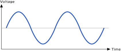
In many cases the target AC Waves would be Sine Curves. For example, a motor control system will require a sine wave to drive a motor because an ideal sine curves should give the most quiet rotation or the least power consumption. Another example is a power conditioner which will generate 60Hz sine wave on the commercial usage power lines.
Now, it is discussed how the Origin Wave generator produces the Origin Wave which will be transferred to a sine curve through the AC generator.
The Origin Wave of the sine curve is generated as follows.
At first, some definition should be done. The maximum output level and minimum one of the AC Generator are +V and –V, respectively. And the amplitude of the sine curve as the output is smaller than the value 2 x V.
Next, an isosceles triangle is prepared. The height of the triangle is 2 x V and it repeats along horizontal axis (time axis) and the base is a fixed time interval. The sine curve is put on the chart along with the triangles back ground.
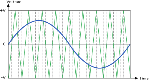
Comparing the values of the triangles to those of the sine curve, define ‘one’ if the sine curve is bigger than the triangle and ‘zero’ if, not. That would get a sequential of unit-height pulses, which is the Origin Wave of the sine curve.
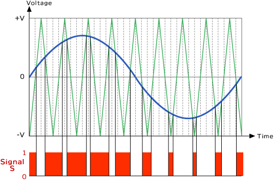
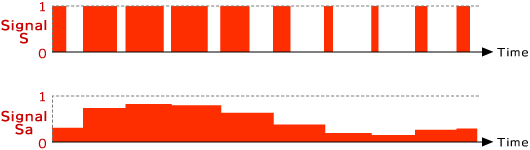
The Origin Wave (Signal S) features that the wider pulse appears at the bigger value in the sine curve. For better understanding if the pulses will be modified to fill in neighboring space without changing the area of the pulse, a shape of a sine curve looms (Signal Sa). As easily imagined, the shape is closer to a sine curve when the isosceles triangle becomes steeper (the base is smaller). Note that the Signal Sa is not a real wave but a conceptual wave.
The technology to generate a wave like the Origin Wave, which consists of pulses of constant height and variable width, is called PWM (Pulse Width Modulation). Inverter control is realized with PWM technology.
1-3) Feedback Control
The fundamental function of Inverter control is that Origin Wave generator produces PWM Origin wave and AC generator will generate a sine wave transformed by the Origin Wave. This is not all in actual implementation. The control system has a motor or another device inside which would be called “a load” in electric world. When the load is operating, it distorts the sine wave of the output of the AC generator; the amplitude of the sine wave may decrease, the phase may slightly change, or the frequency may be unstable, and so on.
There should be more several functions in the system to acquire ideal curve of the sine wave. A monitor function of the output wave of the AC generator (it is the input of the load). Next, the monitored signal should be compared with the ideal waveform. As the result, if the amplitude of the monitored signal is smaller, the output of Origin Wave Generator, PWM pulses, should be longer, and, vice versa. After repeating this process the output wave is quite close to the ideal wave and try to keep the waveform in the same shape.
Such loop as described above, generally speaking, is known well as “a feedback control” system. Owing to the feedback control the Inverter Control can be applied to a variety of different load values.
1-4) Circuits necessary for Inverter Control
The brief idea of Inverter Control has been given above, and next question will be what circuits are available to realize the control.
The answer is; a monitor circuit to monitor AC generator output, an isosceles triangle generator, a comparing circuit of the monitored signal and the isosceles triangle (a generator of signal S), a comparator of signal S of the monitored signal and the ideal signal S of the ideal sine wave, a storage of the ideal signal S, PWM pulse generator, and of course, AC generator itself.
Let's see more detail of each circuit.
The monitor circuit for the AC generator output would be an AD Converter which converts monitored analog signal to digital values. This conversion makes it easier to compare magnitudes between the conversion values and the isosceles triangle values (digital values).
A counter circuit is used to make the isosceles triangle. The counter should count pulses with a rather quick frequency clock, and it increments till some predefined count value and decrements after hitting the count value; which generates the isosceles triangle.
The comparison would be done by a digital calculator circuit.
The signal S of the ideal sine curve is stored in a storage memory.
And PWM pulses will be generated by a special circuit which is dedicated to control a series of PWM pulses.
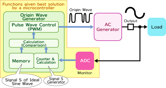
As easily understood, almost all circuits for the Inverter Control function are integrated on a microcontroller chip. Especially, a microcontroller with PWM control IP (Intellectual Property) is one of the best solutions to do Inverter Control.
This is the end of the brief explanation of Inverter Control. It may be too simplified example to understand full of the technology. Please refer to professional books which are found in the shelves of bookstores or libraries to study more.