


Introducing Accu-ROM™, a thermal and noise simulation technology for automotive power semiconductors for MBD (Model Based Development)
- Enables high-precision and high-speed system simulation
- Available in Ansys® Twin Builder™
- Demo video

In order to efficiently develop in-vehicle systems, the automotive industry has introduced technologies to verify the functionality and performance of the entire system through simulations using the model-based development (MBD) method.
This method divides the functions and units constituting the system into blocks, defines the operation of each block as a model, and connects these models to verify the functions and performance of the entire system on the desk.
When designing an ECU, detailed component models such as of semiconductors can represent a more realistic system operation.
We develop MOSFET (metal-oxide-semiconductor field-effect transistors) for automotive applications and also provide device models (SPICE models) that can represent detailed operation when incorporated into MBDs.
Linking to G2 Model Feature Page
In a simulation for MBD, when not only the function simulation of the entire system but also the characteristic simulation of the ECU is performed, if a plant such as a motor or mechanical part is connected as a plant and an operation scenario is assumed, the simulation itself becomes very difficult. In general, it is difficult to capture the simulation of heat and noise.
Simulation generally has a trade-off between accuracy and computation time. However, we have developed Accu-ROM™ (Accurate Reduced-Order Modeling) technology that allows high-precision and high-speed simulations by limiting the application to the thermal characteristics and EMI (Electromagnetic Interference) noise of the system in which machinery is integrated.
For more detailed information, please refer to the following:
→ Technical Review PDF-file linking *Toshiba Review (Vol.76, No.5, November 2021)(PDF: 1.1MB)
This technology is already embedded in Ansys® Twin Builder™. If you want to try it now, please access from the following.
Applying MOSFET's SPICE Model to System Analysis (MBD Analysis) makes the operation more realistic

The left side of Fig. 1 divides the car's EPS (Electric Power Steering) system into blocks. Each block is defined by mathematical expressions or tables (table model) and is connected.
By turning the handle, the torque signal is transmitted to the torque assist block in the red frame, the required motor rotation speed is calculated, and the motor moves. We replaced this torque assist block with a three-phase inverter model (circuit model), which is an actual circuit configuration, and the MOSFET used is also a detailed SPICE model. This is shown on the right side of Fig. 1.
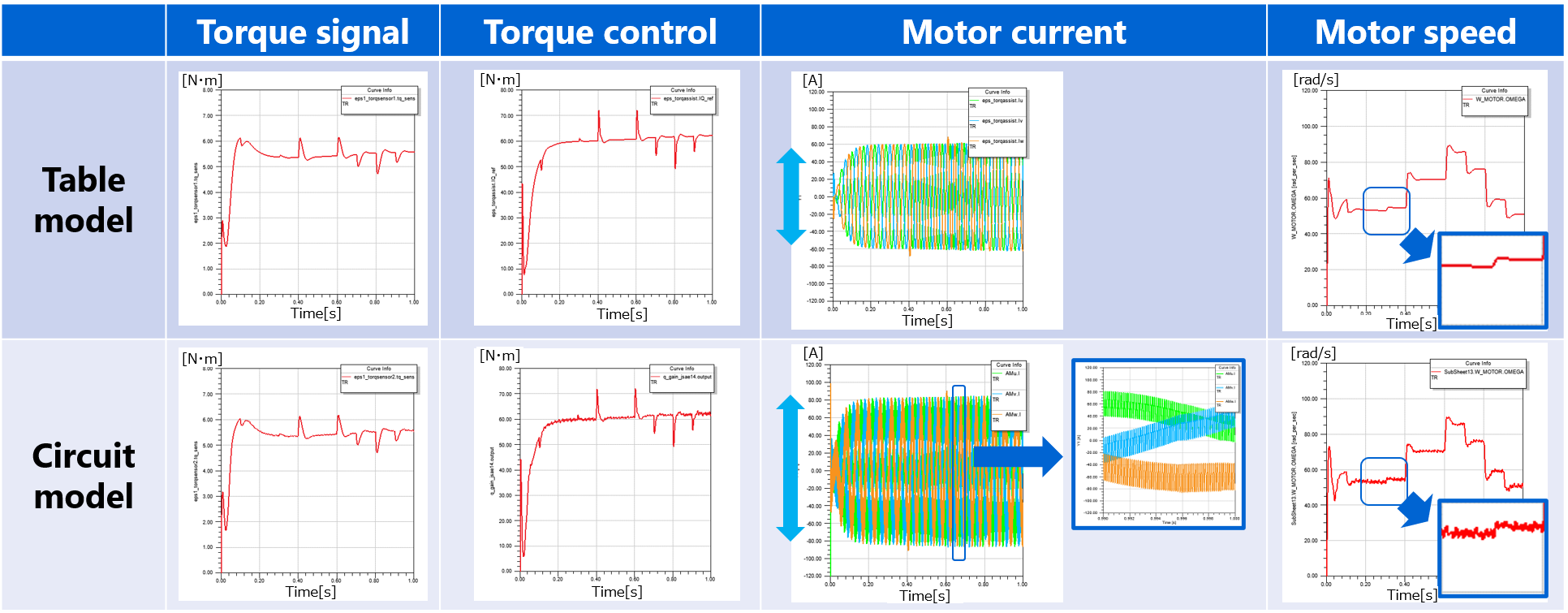
The results of simulations using these models are shown in Figure 2. The results of table model and circuit model are shown in the upper and lower part of Figure 2.
Overall both behave in the same way, but the output current (motor current) of the inverter shows that the ripple component is superimposed to match the switching operation of the inverter in the case of the circuit model. When the model is refined in this way, it can be seen that it is not only possible to confirm the specifications such as functions and performance, but is also possible to check the actual operation in more detail.
By precisely reproducing the operation of the MOSFET, simulations of heat and EMI noise are possible. The problem is convergence and analysis time. Incorporating SPICE model into plant simulation increases analysis time by 10 times⁉
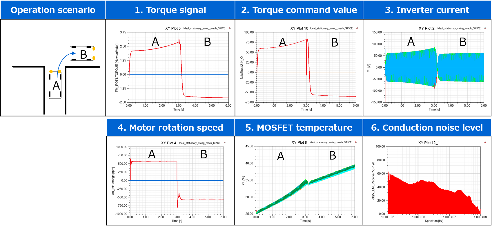
When the circuit model is used for detailed verification, verification of the thermal feasibility of the system and observation of EMI noise, etc. are possible in the simulation. Figure 3 shows an example of a car turning right.
This setting is used to turn the handle clockwise for 3 seconds and return it to its original position for 3 seconds. Looking at the motor rotation speed, we can see that the motor rotates in the positive direction for the first three seconds and in the opposite direction for next three seconds.
At this time, the junction temp. of MOSFET continues to rise in accordance with the operation, most EMI noise emission is observed.
This is achieved by calculating the heat generated based on the current and voltage flowing through MOSFET and using it as a heat source for the peripheral thermal circuit model which is connected to the circuit model. And similarly EMI noise emission is also calculated by adding a LISN (Line Impedance Stabilization Network) circuit (specified by CISPR 25) to the circuit model.
In this way, both heat and EMI noise emission are calculated by adding the necessary circuits to the detailed MOSFET circuit model, and the necessity of the this type of circuit model can be seen.
However, the problem here is the calculation time. When this same operation was verified with a table model (although heat and noise cannot be verified), it took 3 hours, but with a circuit model, it took 32 hours and 51 minutes.
Note 1: CISPR 25 (International Special Commission on Radio Interference Standard 25)
Why does it take longer to calculate?
Cause 1: Difference between electrical and mechanical response time
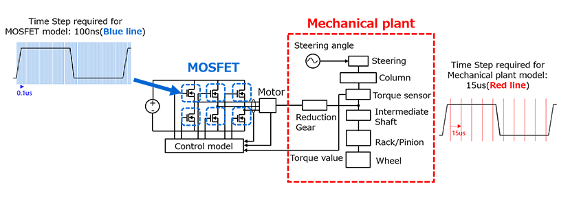
There is a difference in the response time of each block. For example, the mechanical components, such as reduction gears and intermediate shafts, of the EPS system shown in Fig. 4 have response time in the order of ms, whereas torque-assisted inverters have response time in the order of ns because of the switching operation of MOSFET. For this reason, if the calculation is done in increments that match the operation of the inverter, the mechanical plant will repeat the same calculation except for the switching time.
Cause 2: Calculating time of SPICE simulation
Another cause is the calculation time of SPICE used for the MOSFET model. SPICE usually calculate using 100-200 parameters, and it doesn't matter much if it checks the normal waveforms. However, if it is used for system verification, which in this case is for 6s with a step of 100ns, so it would take 60 million iterations of the calculation and corresponding processing time.
Reduced order model is the key to solve the computation time challenge. It is resolved with Accu-ROM™ technology!!
Calculation-time challenge can be solved by Accu-ROM™ technology (algorithms is explained in STEP 1 to 3).
Accu-ROM™ Technology STEP 1: Reduced-order modeling for the mechanical model
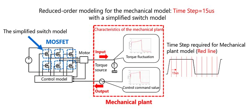
First step is reducing the mechanical plant model order. As mentioned above, there are large differences in response times between MOSFET and mechanical plants. Therefore, if we want to see the behavior of the entire mechanical plant, no detailed movement of MOSFET is required, and it is enough to know the status of the time step as well as the switch. Therefore, MOSFET model is assumed to be a simplified switch model in which the switches are turned on and off, and the calculation is done by coarsening the time steps.
Since the switching frequency of this inverter is 6.5kHz (153.85us per cycle), the calculation step is set to 1/10 which is 15us. This way the characteristics of the entire mechanical plant is extracted. Then, whole mechanical plant model is deleted, and a torque source is connected to the motor, and the required torque fluctuation characteristic of the entire mechanical plant extracted earlier is connected there. The signal fed back from the mechanical plant to the control model has the command value to generate the torque required for the entire mechanical plant. This makes it possible to create a model that shows the characteristics of the entire mechanical plant.
Accu-ROM™ Technology STEP 2: Reduced-order modeling for the MOSFET
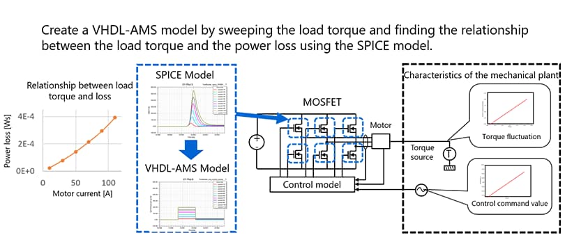
Next step is the reducing the MOSFET model order. For observing the behavior of MOSFET, time steps need to be finer, but if the applied torque connected to the motor is the same, it will show the same behavior regardless of the contents of the mechanical plant. Therefore, a torque source is connected to the motor, MOSFET is set to SPICE model., and calculation increments are also set to fine values that match the switching characteristics. Using this circuit, the amount of torque is varied within the specified range of the motor, and the amount of switching loss and the amount of noise with respect to the load torque value are obtained in advance. The relation between the load torque and the loss is tabulated to create a VHDL-AMS model and it replaces the SPICE model.
Note 2: VHDL-AMS (Very-High Speed IC Hardware Description Language - Analog and Mixed Signal) Model
Accu-ROM™ Technology STEP 3: Simulation using reduced-order model
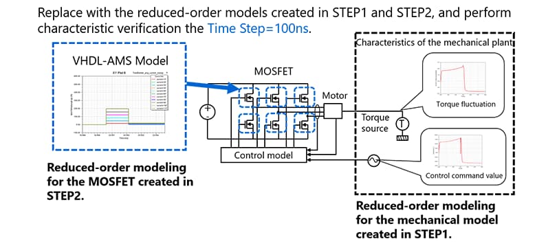
Characteristic verification is done after replacing the models with the reduced order models created in STEP 1 and STEP 2 and setting the Time Step to fine. The load torque value required for the entire mechanical plant for system operation according to the operation scenario, is checked every time by referring to the VHDL-AMS model and omitting SPICE model calculations, therefore it is possible to get the amount of switching loss at high speed.
Benefit in computing time by using Accu-ROM™ technology

By using this Accu-ROM™ technology, the results of the temperature change in MOSFET before model order reduction can be almost reproduced, and the calculation also gets completed in 3 hours and 27 minutes.
Our Accu-ROM™ technology automatically reduces model order fine properties and automates simulation (Note 3)!!
Note 3: Realized by Ansys® TWIN BUILDER™.
This demonstration video shows the automation of Accu-ROM™ technology (STEP 1 through 3).
By automating the entire series of operations of creating the reduced order model, replacing the model, and executing the simulation, our solution enables stress free and highly accurate thermal and EMI noise verification by using the circuit model and that too in the same calculation time as that of conventional table model.
For more detailed information, please refer to the following:
→ Technical Review PDF-file linking *Toshiba Review (Vol.76, No.5, November 2021)(PDF: 1.1MB)
We are proceeding with the development of MBD-related technologies, and we will not only develop semiconductors, but will also provide simulation models and technologies that can contribute to the design of our customers.
We will continue to strive for enhancing the functions of Accu-ROM™.
Related information
* Accu-ROM™ is a trademark of TOSHIBA CORPORATION Device & Storage Corporation.
* Ansys® and all other ANSYS, Inc. product names are trademarks or registered trademarks of ANSYS, Inc. or its subsidiaries in the United States or other countries.
* Other company names, product names, and service names may be trademarks of their respective companies.