
- General Top
- SEMICONDUCTOR
- STORAGE
- COMPANY
-
My ToshibaSemicon
- Semiconductor Top
-
ApplicationsAutomotive
Body Electronics
xEV
In-Vehicle Infotainment
Advanced Driver-Assistance Systems (ADAS)
Chassis
IndustrialInfrastructure
BEMS/HEMS
Factory Automation
Commercial Equipment
Consumer/PersonalIoT Equipment
Healthcare
Wearable Device
Mobile
Computer Peripherals
-
ProductsAutomotive Devices
Discrete Semiconductor
Diodes
Transistors
Logic ICs
Analog Devices
- Automotive SmartMCD™ (Integreted SoC Conbining Microcontroller and Driver)
- Automotive Brushless Motor Driver ICs
- Automotive Brushed DC Motor Driver ICs
- Automotive Stepping Motor Driver ICs
- Automotive Driver ICs
- Automotive System Power Supplies ICs
- Automotive audio power amplifier ICs
- Automotive Network Communication
Digital Devices
Wireless Devices
※
 : Products list (parametric search)Power Semiconductors
SiC Power Devices
※
: Products list (parametric search)Isolators/Solid State RelaysPhotocouplers
Digital Isolators
Solid State Relays
Fiber Optic Transmitting Modules
※
: Products list (parametric search)MOSFETsIGBTs/IEGTsBipolar Transistors※
: Products list (parametric search)Diodes※
: Products list (parametric search)MicrocontrollersMotor Driver ICsIntelligent Power ICs※
: Products list (parametric search)Power Management ICsLinear ICs※
: Products list (parametric search)General Purpose Logic ICsLinear Image SensorsOther Product ICsOther Product ICs
※
: Products list (parametric search) -
Design & Development
-
Knowledge
- Where To Buy


- Part Number & Keyword Search
- Cross Reference Search
- Parametric Search
- Stock Check & Purchase
This webpage doesn't work with Internet Explorer. Please use the latest version of Google Chrome, Microsoft Edge, Mozilla Firefox or Safari.
require 3 characters or more. Search for multiple part numbers fromhere.
The information presented in this cross reference is based on TOSHIBA's selection criteria and should be treated as a suggestion only. Please carefully review the latest versions of all relevant information on the TOSHIBA products, including without limitation data sheets and validate all operating parameters of the TOSHIBA products to ensure that the suggested TOSHIBA products are truly compatible with your design and application.Please note that this cross reference is based on TOSHIBA's estimate of compatibility with other manufacturers' products, based on other manufacturers' published data, at the time the data was collected.TOSHIBA is not responsible for any incorrect or incomplete information. Information is subject to change at any time without notice.
require 3 characters or more.
How to install and use Accu-ROM™ on Ansys® Twin Builder™
1. Using Accu-ROM™

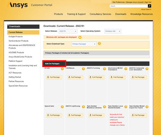
- The installer can be downloaded from Ansys‘s Customer Portal site - “Current Release”.
https://support.ansys.com/portal/site/AnsysCustomerPortal - Select "Downloads > Current Release"
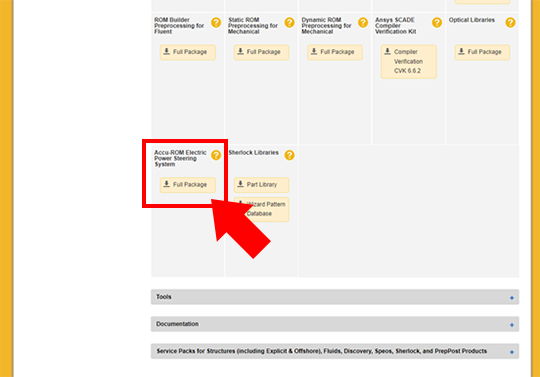
- Select "Add-On Packages > Accu-ROM Electric Power Steering System"
*This function runs on Twin Builder™ and requires Twin Builder™ to operate.
2. Starting Accu-ROM™
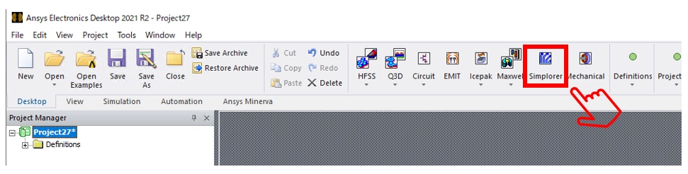
- Launch Ansys Electronics Desktop and press Simplorer.
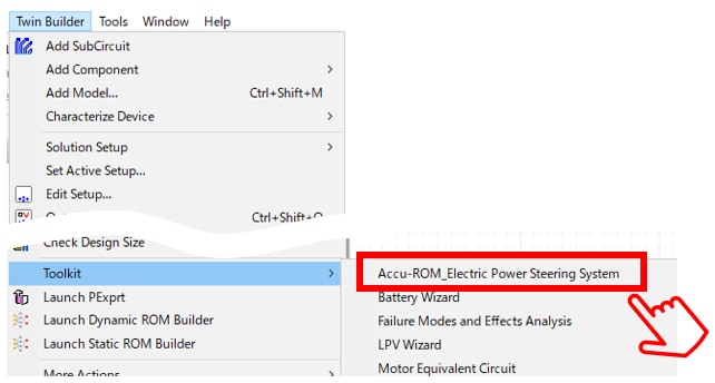
- From Twin Builder menu
Toolkit > Accu-ROM_Electric Power Steering System
Select OK.
3. How to set Accu-ROM™
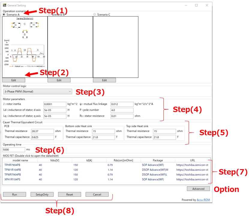
- When the setting window opens, set in the following Step order. The setting of Step (6), (7) and (8) is mandatory. Configure the other Step as needed.
Step(1). Select steering scenario for steering. Currently, only Scenario A is preset.
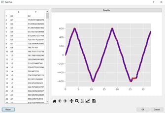
Step(2). Press "Edit" to start WAVE VIEWER. Edit the steer scenario waveform as needed.
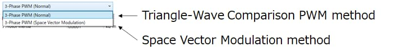
Step(3). Selects the motor control method. Two types of control methods are currently preset.
- Triangle-Wave Compare PWM method: A general modulation method for 3-phase PWM.
This method generates PWM signals by comparing the carrier wave of the triangle wave with the UVW phase waveform. - Space Vector Modulation method: A method to generate PWM based on the spatial voltage vector.
Compared with the triangle-wave comparison PWM method, the DC voltage utilization factor can be improved.
Step(4). Set various parameters of the motor.
J: Moment of inertia ψ: Chain magnetic flux
Ld: d-axis inductance p: Number of contacts
Lq: q-axis inductance Rs: Winding resistance
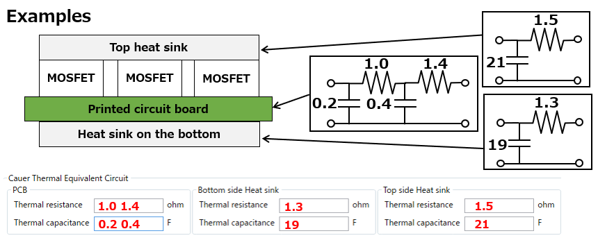
Step(5). Set the thermal resistance and heat capacity of the printed circuit board and heat sink. To configure a multi-stage RC circuit, input multiple resistance and capacitance values by separating them with a space.
Step(6). Set the simulation time.
Step(7). Selects the power semiconductor (MOSFET) used for 3-phase inverter circuitry. Double-click to jump to the product page.
Step(8). Run : Starts the simulation.
Setup Only : Saves the settings. No simulation is performed.
Option: The Advanced Settings window opens. Normally, this setting is not required. Refer to the following for details.
<Description of the detailed setting screen>
Accu-ROM™ is simulated under the following 4Step. Here you can make detailed settings for each Step.
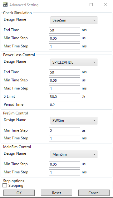
1. Check Simulation :
Simulation for initial operation check.
2. Power Loss Control:
Simulation for reduced-order modeling of MOSFET model.
3. PreSim Control:
Simulation for reduced-order modeling of mechanical plant model. Operating Time of the main setting window is applied to End Time.
4. MainSim Control:
Simulation for reduced-order modeling of MOSFET and mechanical plant model. Operating Time of the main setting window is applied to End Time.
4. Analysis display of Accu-ROM™ (before reduced-order modeling)
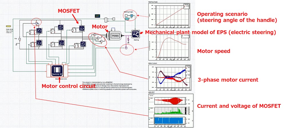
- The screen before reduced-order modeling is as follows.
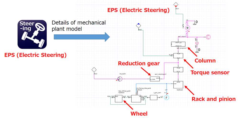
- The EPS (Electric Steering) mechanical plant model before reduced-order modeling consists of the following:
5. Analysis display of Accu-ROM™ (after reduced-order modeling)
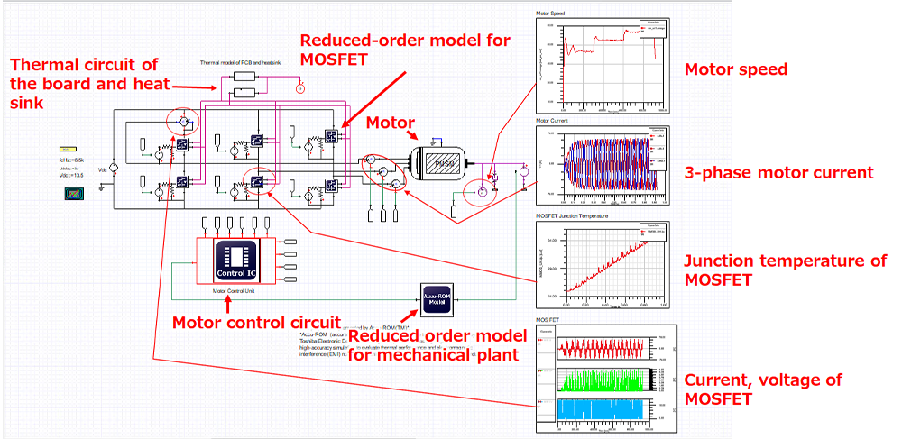
- The screen after reduced order modeling is as follows. MOSFET and mechanical plant model orders are reduced and automatically switched to the reduced-order model.
6. Analysis of Accu-ROM™
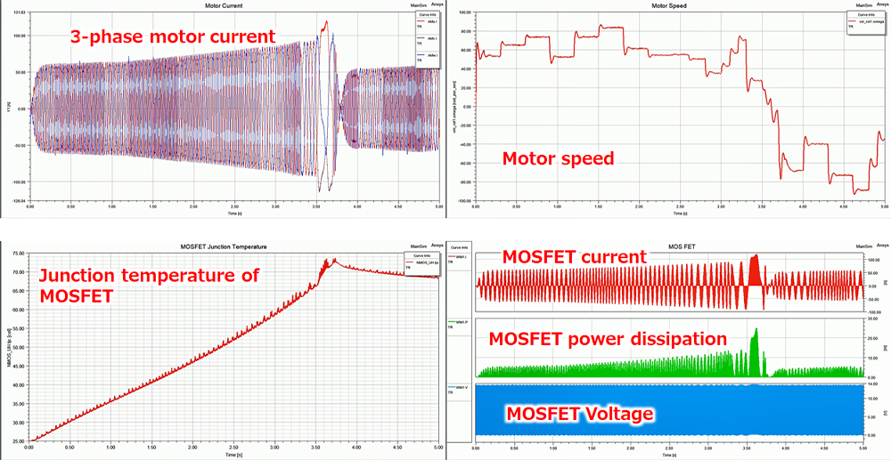
- Currently, the following analysis results are displayed as presets.
Related information
*Ansys® and all other ANSYS, Inc. product names are trademarks or registered trademarks of ANSYS, Inc. or its subsidiaries in the United States or other countries.
*Accu-ROM™ is a trademark of TOSHIBA CORPORATION Device & Storage Corporation.
*Other company names, product names, service names, and the like may be used by each company as trademarks.