- General Top
- SEMICONDUCTOR
- STORAGE
- COMPANY
-
My ToshibaSemicon
- Semiconductor Top
-
ApplicationsAutomotive
Body Electronics
xEV
In-Vehicle Infotainment
Advanced Driver-Assistance Systems (ADAS)
Chassis
IndustrialInfrastructure
BEMS/HEMS
Factory Automation
Commercial Equipment
Consumer/PersonalIoT Equipment
Healthcare
Wearable Device
Mobile
Computer Peripherals
-
ProductsAutomotive Devices
Discrete Semiconductor
Diodes
Transistors
Logic ICs
Analog Devices
- Automotive SmartMCD™ (Integreted SoC Conbining Microcontroller and Driver)
- Automotive Brushless Motor Driver ICs
- Automotive Brushed DC Motor Driver ICs
- Automotive Stepping Motor Driver ICs
- Automotive Driver ICs
- Automotive System Power Supplies ICs
- Automotive audio power amplifier ICs
- Automotive Network Communication
Digital Devices
Wireless Devices
※
 : Products list (parametric search)Power Semiconductors
SiC Power Devices
※
: Products list (parametric search)Isolators/Solid State RelaysPhotocouplers
Digital Isolators
Solid State Relays
Fiber Optic Transmitting Modules
※
: Products list (parametric search)MOSFETsIGBTs/IEGTsBipolar Transistors※
: Products list (parametric search)Diodes※
: Products list (parametric search)MicrocontrollersMotor Driver ICsIntelligent Power ICs※
: Products list (parametric search)Power Management ICsLinear ICs※
: Products list (parametric search)General Purpose Logic ICsLinear Image SensorsOther Product ICsOther Product ICs
※
: Products list (parametric search) -
Design & Development
-
Knowledge
- Where To Buy


- Part Number & Keyword Search
- Cross Reference Search
- Parametric Search
- Stock Check & Purchase
This webpage doesn't work with Internet Explorer. Please use the latest version of Google Chrome, Microsoft Edge, Mozilla Firefox or Safari.
require 3 characters or more. Search for multiple part numbers fromhere.
The information presented in this cross reference is based on TOSHIBA's selection criteria and should be treated as a suggestion only. Please carefully review the latest versions of all relevant information on the TOSHIBA products, including without limitation data sheets and validate all operating parameters of the TOSHIBA products to ensure that the suggested TOSHIBA products are truly compatible with your design and application.Please note that this cross reference is based on TOSHIBA's estimate of compatibility with other manufacturers' products, based on other manufacturers' published data, at the time the data was collected.TOSHIBA is not responsible for any incorrect or incomplete information. Information is subject to change at any time without notice.
require 3 characters or more.
What is bushold of the general-purpose logic ICs?
A bushold circuit is added to the data input of an IC. Consisting of two inverters in a feedback loop, the bushold circuit holds the state at an input pin at its last known state whenever it is left open (i.e., floating).
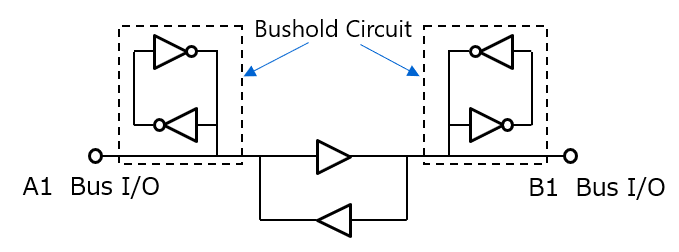
The following Fig. shows an equivalent circuit for a bushold circuit.
In the case of general-purpose logic circuits, unused input pins assume the High-Z state if they are left open or floating. Typically, this situation is prevented by connecting external pull-up or pull-down resistors because the High-Z state causes input capacitance to be gradually charged by leakage current, eventually turning on the input P-channel and N-channel MOSFETs simultaneously and thereby causing undesired current or abnormal oscillation.
In contrast, the bushold circuit employs a weak feedback gate tied back to the input to hold the last input state until it changes state next time.
Therefore, ICs with a bushold circuit eliminate the need for external pull resistors.
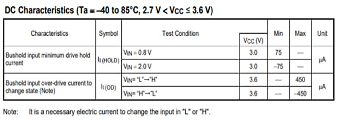
There are two electrical characteristics concerning the bushold circuit: 1) bushold input minimum drive hold current (II (HOLD) ) that specifies the minimum current that the bushold circuit can supply to a device or a bus, and 2) bushold input overdrive current to change state (II (OD) ) that specifies the minimum overdrive current necessary to change the state held in the bushold circuit. An example of bushold characteristics shown in the datasheet (Table-1) is given below.
Related Links
The following documents also contain related information.