- General Top
- SEMICONDUCTOR
- STORAGE
- COMPANY
-
My ToshibaSemicon
- Semiconductor Top
-
ApplicationsAutomotive
Body Electronics
xEV
In-Vehicle Infotainment
Advanced Driver-Assistance Systems (ADAS)
Chassis
IndustrialInfrastructure
BEMS/HEMS
Factory Automation
Commercial Equipment
Consumer/PersonalIoT Equipment
Healthcare
Wearable Device
Mobile
Computer Peripherals
-
ProductsAutomotive Devices
Discrete Semiconductor
Diodes
Transistors
Logic ICs
Analog Devices
- Automotive SmartMCD™ (Integreted SoC Conbining Microcontroller and Driver)
- Automotive Brushless Motor Driver ICs
- Automotive Brushed DC Motor Driver ICs
- Automotive Stepping Motor Driver ICs
- Automotive Driver ICs
- Automotive System Power Supplies ICs
- Automotive audio power amplifier ICs
- Automotive Network Communication
Digital Devices
Wireless Devices
※
 : Products list (parametric search)Power Semiconductors
SiC Power Devices
※
: Products list (parametric search)Isolators/Solid State RelaysPhotocouplers
Digital Isolators
Solid State Relays
Fiber Optic Transmitting Modules
※
: Products list (parametric search)MOSFETsIGBTs/IEGTsBipolar Transistors※
: Products list (parametric search)Diodes※
: Products list (parametric search)MicrocontrollersMotor Driver ICsIntelligent Power ICs※
: Products list (parametric search)Power Management ICsLinear ICs※
: Products list (parametric search)General Purpose Logic ICsLinear Image SensorsOther Product ICsOther Product ICs
※
: Products list (parametric search) -
Design & Development
Design & Development
Innovation Centre
At the Toshiba Innovation Centre we constantly strive to inspire you with our technologies and solutions. Discover how to place us at the heart of your innovations.
-
Knowledge
Knowledge
Highlighted Topics
Further Materials
Other
- Where To Buy


- Part Number & Keyword Search
- Cross Reference Search
- Parametric Search
- Stock Check & Purchase
This webpage doesn't work with Internet Explorer. Please use the latest version of Google Chrome, Microsoft Edge, Mozilla Firefox or Safari.
require 3 characters or more. Search for multiple part numbers fromhere.
The information presented in this cross reference is based on TOSHIBA's selection criteria and should be treated as a suggestion only. Please carefully review the latest versions of all relevant information on the TOSHIBA products, including without limitation data sheets and validate all operating parameters of the TOSHIBA products to ensure that the suggested TOSHIBA products are truly compatible with your design and application.Please note that this cross reference is based on TOSHIBA's estimate of compatibility with other manufacturers' products, based on other manufacturers' published data, at the time the data was collected.TOSHIBA is not responsible for any incorrect or incomplete information. Information is subject to change at any time without notice.
require 3 characters or more.
Meeting the motor drive challenge of power tool design
In common with many products, the challenges for power tool designers are ramping up. With users wanting lighter tools with greater run-time at a lower cost, there are some fundamental changes in the technologies being employed.
For many years, brushed motors have been the mainstay. They are simple to use and easy to power but, on the downside, they are relatively inefficient and the brushes are a weak spot as they arc and cause EMI, as well as wearing, thereby requiring maintenance.
Brushless DC motors (BLDC) are becoming popular for several reasons. Firstly, they offer better efficiency (up to 15% better than brushed motors) and offer more rotational power for a given size. Additionally, they can offer a wider speed range and are quieter – both electrically and mechanically. All these benefits allow the development of better power tools. However, while it is relatively simple to make a BLDC motor rotate, driving it properly is somewhat of a challenge that must be overcome.
To control a BLDC motor, the DC supply must be converted to a 3-phase signal to drive the 3 stator windings. In some cases, a position feedback sensor is also required. The voltage and frequency of the 3-phase waveform controls the rotational speed and the current is proportional to the torque. The frequency must be high enough so as not to cause audible noise yet not so high that losses in the transistors become excessive – typically a few tens of kilohertz are used.
There are many methods of driving a BLDC motor, relating to the shape of the AC waveform. The simplest is trapezoidal where two windings are energized and the third is open circuit. This provides a rotational force which moves the rotor although, due to the simple shape of the square wave drive, some ripple is present in the torque which can lead to vibration and noise at low speeds.
The torque ripple can be eliminated by using a sine-wave drive (‘sinusoidal commutation’) although this is more complex, requiring a microcontroller to generate the sine waves. It also requires higher precision in the position sensing.
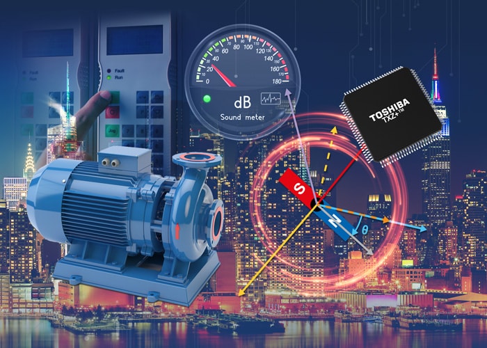
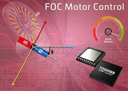
Nowadays, Vector or Field-Oriented Control (FOC) is becoming far more commonplace as it delivers smooth operation over the whole speed range, fast acceleration and deceleration and 100% torque at zero speed. It can operate with position sensors but, equally there are sensorless techniques available.
However, FOC requires some complex mathematical calculations to be performed constantly, allowing the orthogonal components of the field flux linkage and torque to be derived and controlled. Even simple FOC controllers can be quite complex requiring a pulse width modulator (PWM), software-based PI control, ADCs and a vector-capable processor. Many microcontrollers lack the instruction set for this while DSPs have the instruction set but insufficient I/O capability.
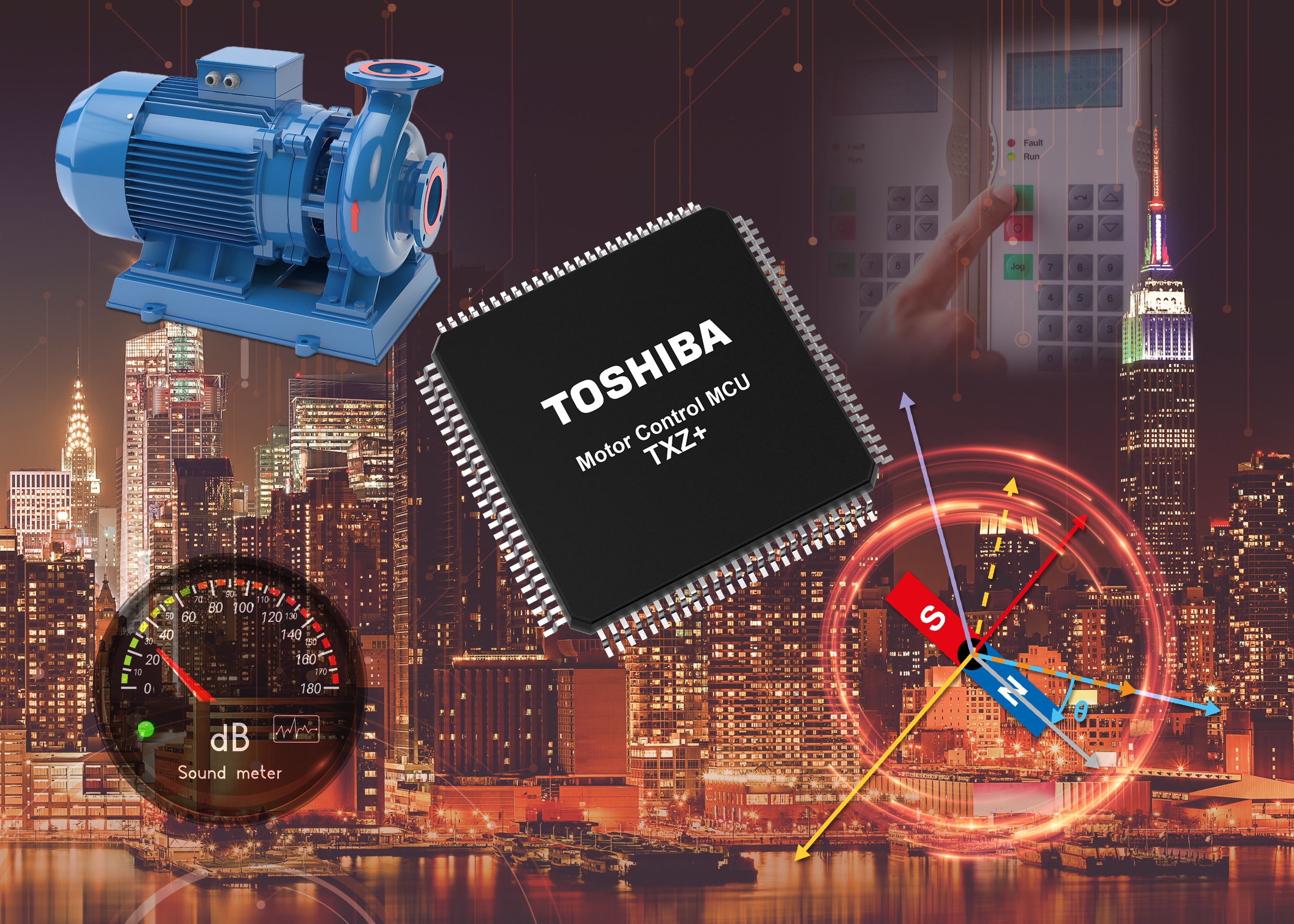
Toshiba’s Advanced Vector Engine (A-VE) is a dedicated FOC controller that is based upon the ARM Cortex-M4 microcontroller platform. Part of the M4K group of devices in the TXZ4 series, the device has the capability to provide FOC to two motors, with processing capacity to spare.
To find out how Toshiba’s A-VE devices can take the strain of driving BLDC motors in demanding applications such as power tools, please download our white paper that gives a full overview of the considerations necessary for modern motor control: