- General Top
- SEMICONDUCTOR
- STORAGE
- COMPANY
-
My ToshibaSemicon
- Semiconductor Top
-
ApplicationsAutomotive
Body Electronics
xEV
In-Vehicle Infotainment
Advanced Driver-Assistance Systems (ADAS)
Chassis
IndustrialInfrastructure
BEMS/HEMS
Factory Automation
Commercial Equipment
Consumer/PersonalIoT Equipment
Healthcare
Wearable Device
Mobile
Computer Peripherals
-
ProductsAutomotive Devices
Discrete Semiconductor
Diodes
Transistors
Logic ICs
Analog Devices
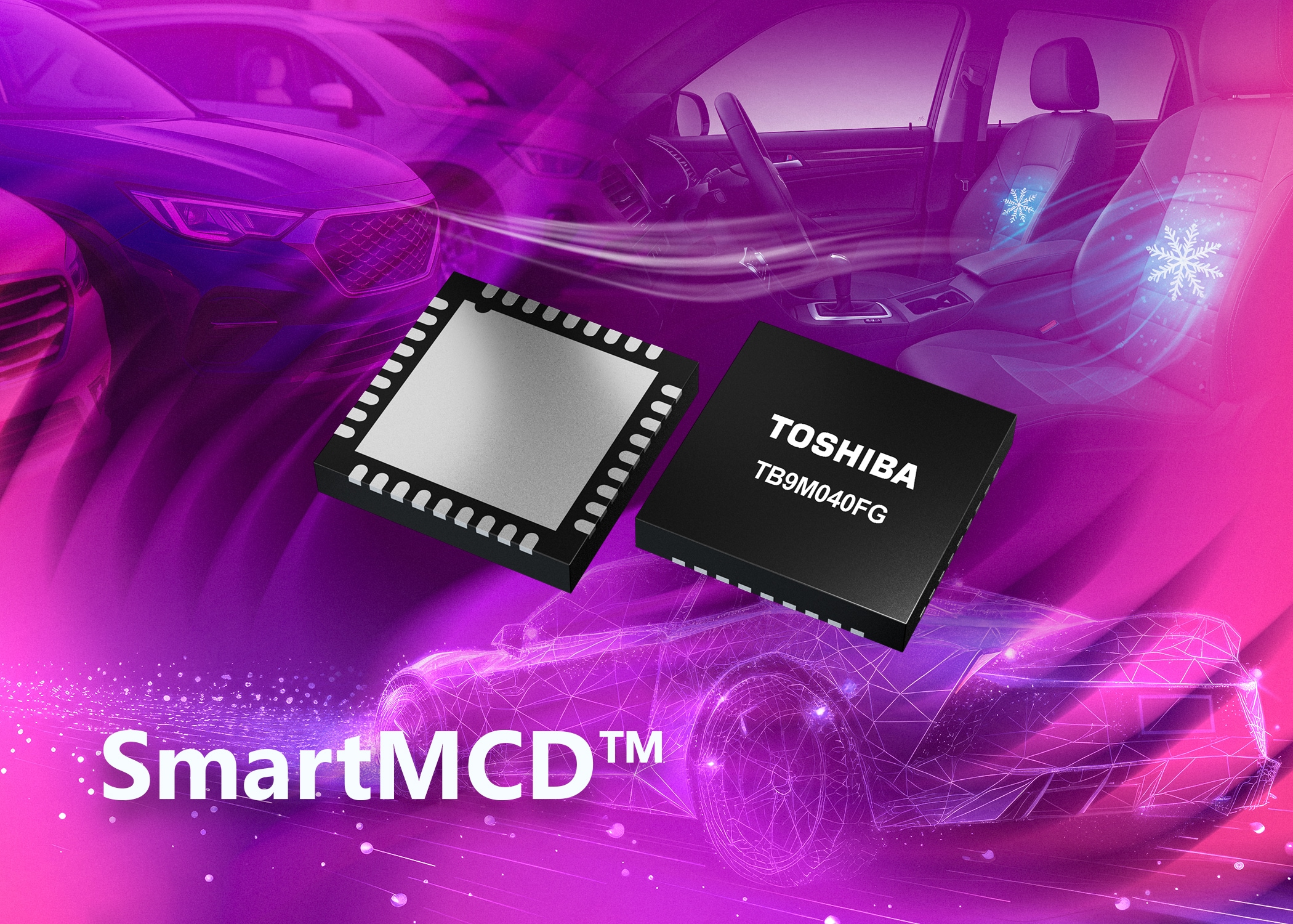
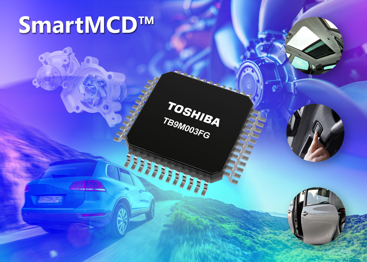
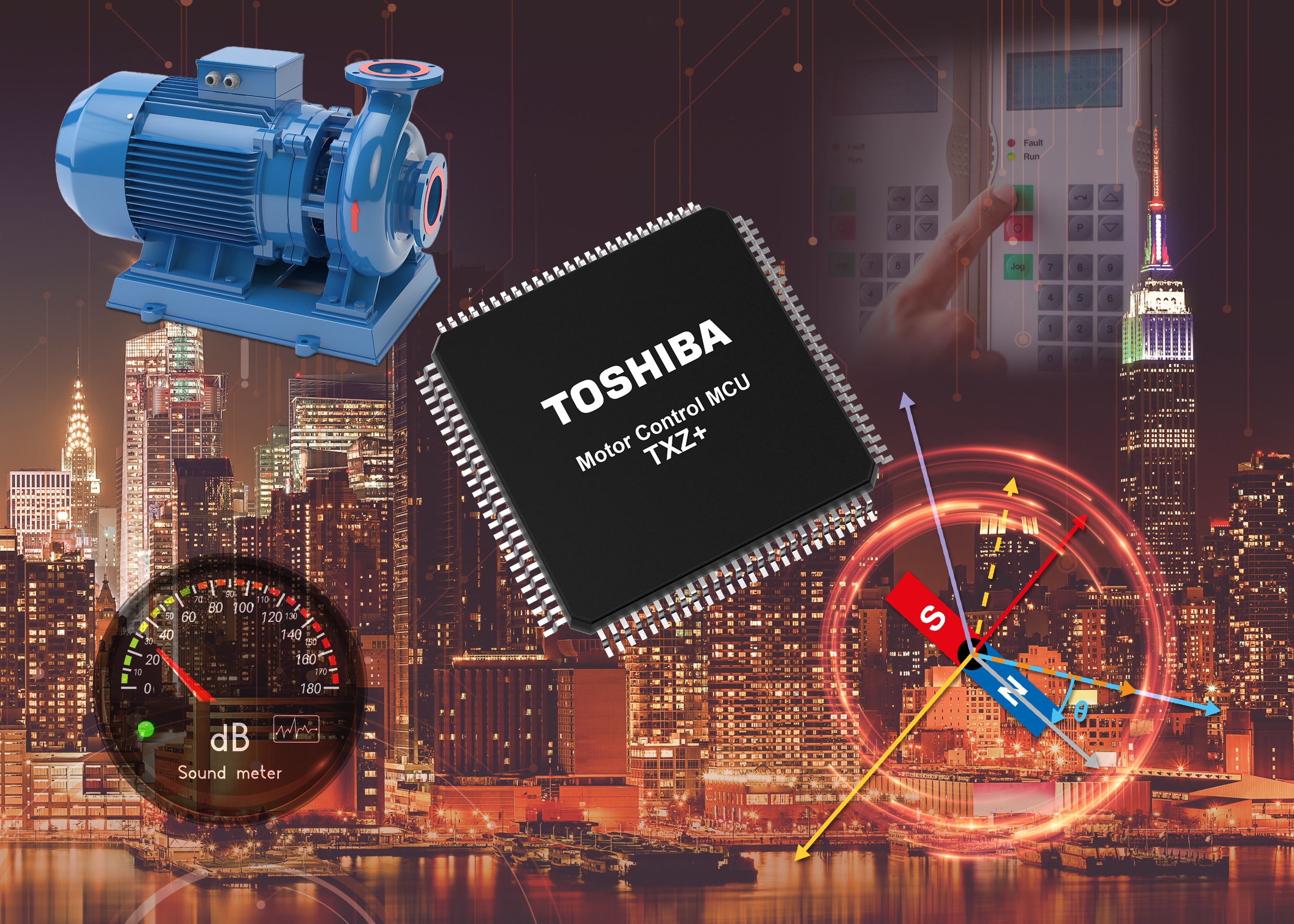
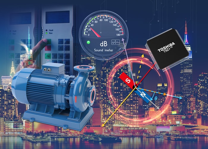
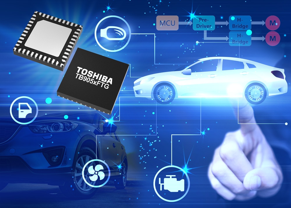
- Automotive SmartMCD™ (Integreted SoC Conbining Microcontroller and Driver)
- Automotive Brushless Motor Driver ICs
- Automotive Brushed DC Motor Driver ICs
- Automotive Stepping Motor Driver ICs
- Automotive Driver ICs
- Automotive System Power Supplies ICs
- Automotive audio power amplifier ICs
- Automotive Network Communication
Digital Devices
Wireless Devices
※
 : Products list (parametric search)Power Semiconductors
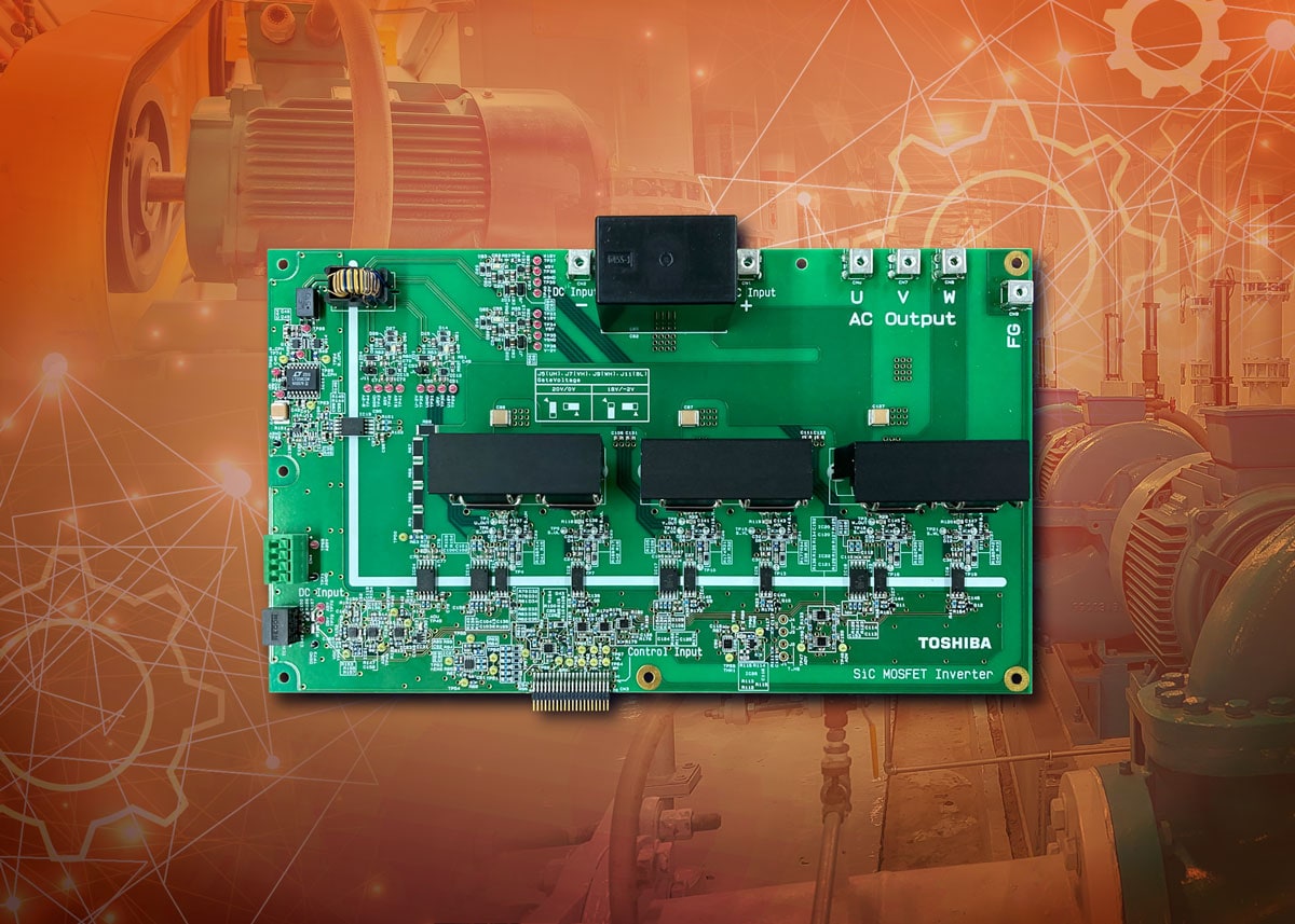
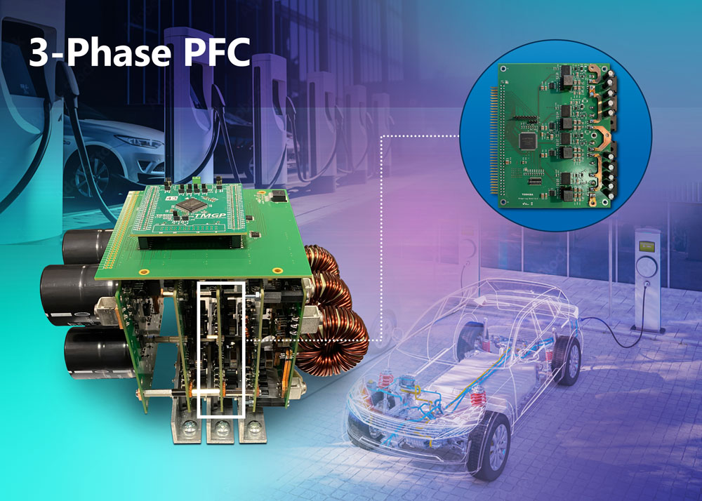
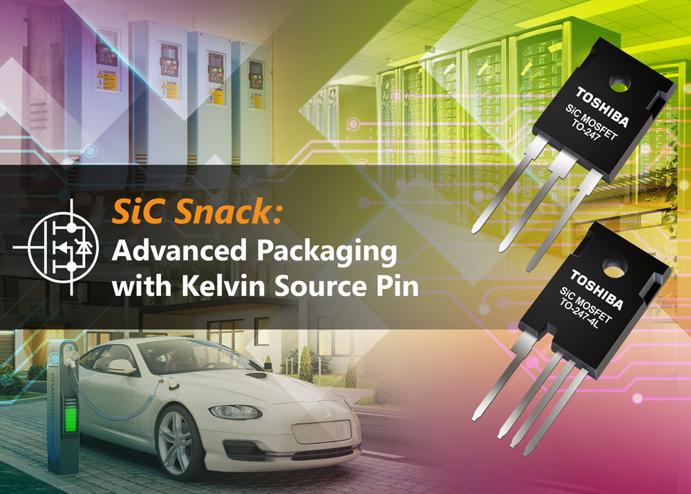
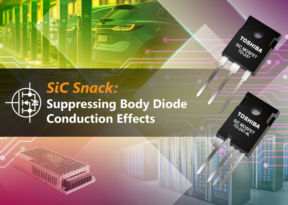
SiC Power Devices
※
: Products list (parametric search)Isolators/Solid State RelaysPhotocouplers
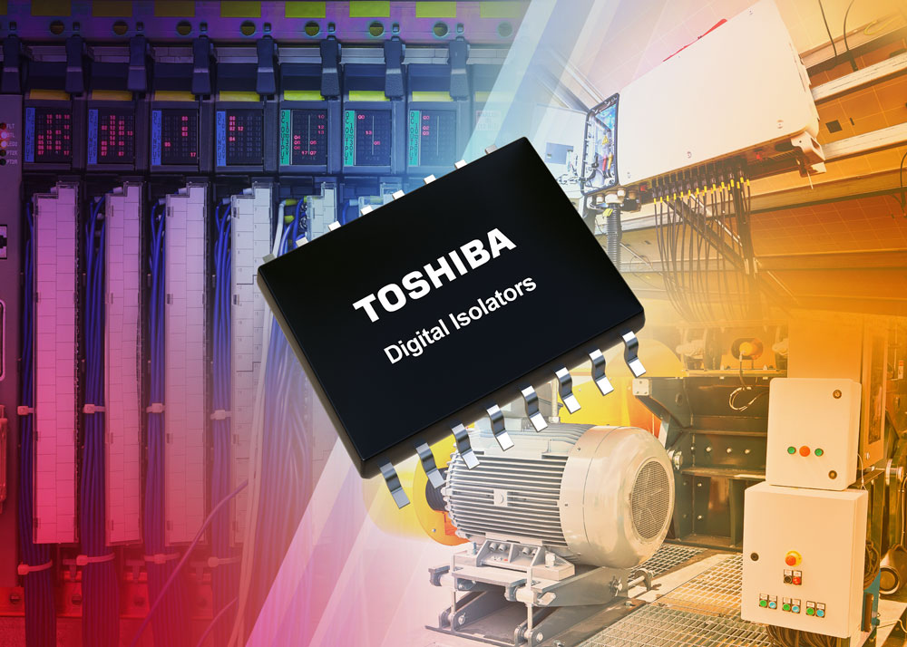
Digital Isolators
Solid State Relays
Fiber Optic Transmitting Modules
※
: Products list (parametric search)MOSFETsIGBTs/IEGTsBipolar Transistors※
: Products list (parametric search)Diodes※
: Products list (parametric search)MicrocontrollersMotor Driver ICsIntelligent Power ICs※
: Products list (parametric search)Power Management ICsLinear ICs※
: Products list (parametric search)General Purpose Logic ICsLinear Image SensorsOther Product ICsOther Product ICs
※
: Products list (parametric search) -
Design & Development
Design & Development
Innovation Centre
At the Toshiba Innovation Centre we constantly strive to inspire you with our technologies and solutions. Discover how to place us at the heart of your innovations.
-
Knowledge
Knowledge
Highlighted Topics
Further Materials
Other
- Where To Buy


- Part Number & Keyword Search
- Cross Reference Search
- Parametric Search
- Stock Check & Purchase
This webpage doesn't work with Internet Explorer. Please use the latest version of Google Chrome, Microsoft Edge, Mozilla Firefox or Safari.
require 3 characters or more. Search for multiple part numbers fromhere.
The information presented in this cross reference is based on TOSHIBA's selection criteria and should be treated as a suggestion only. Please carefully review the latest versions of all relevant information on the TOSHIBA products, including without limitation data sheets and validate all operating parameters of the TOSHIBA products to ensure that the suggested TOSHIBA products are truly compatible with your design and application.Please note that this cross reference is based on TOSHIBA's estimate of compatibility with other manufacturers' products, based on other manufacturers' published data, at the time the data was collected.TOSHIBA is not responsible for any incorrect or incomplete information. Information is subject to change at any time without notice.
require 3 characters or more.
Get started, or continue, with this H-bridge motor driver
Reading through on-line forums, it seems that many students and hobbyists struggle to get to grips with bi-directional motor control. When combined with a microcontroller, the first stage of implementing a transistor- or FET-based driver to deliver enough current to a motor seems simple enough. The next step is making use of or creating through bit-banging, a pulse-width modulation (PWM) signal to control motor rotational speed also comes with relative simplicity. However, the leap to implementing what experienced engineers would know as an H-bridge seems to require some time to absorb.
An H-bridge is implemented with four switching devices, most commonly MOSFETs for small DC motors, with diagonally opposing pairs being switched on to effect clockwise, or counter-clockwise, rotation. Once this hurdle in design has been overcome, the leap to using the same PWM approach to also control the speed is small. The final trick the design offers is making use of the back-EMF the motor generates to implement a braking effect on the rotor. This can be achieved by shorting the rotating motor’s terminals together via either the high- or low-side switches. This serves to slow the rotor to a halt more quickly than it would otherwise, but should not be confused with a mechanical brake.
Toshiba has long had H-bridge motor drivers in its portfolio, with the TA7291 being perhaps the most famous of them all. Initially developed for the fledgling video cassette recorder (VCR) industry, it has gone on to become a de facto H-bridge device being featured in books and literature for engineering students and makers in Japan for many years. Process technology has moved on a long way over the past 40 years meaning that the device has eventually reached the end of its professional life. However, there is now a new device vying to become as famous as its forebear.
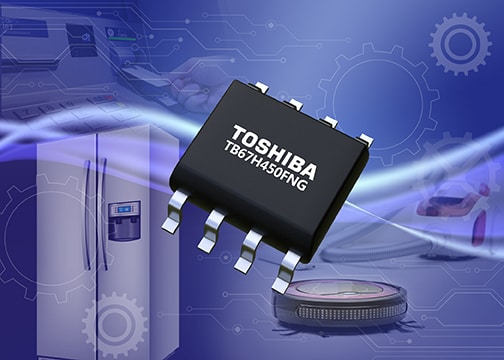
The TB67H450FNG is a compact, 8-pin SOP packaged H-bridge that makes use of the latest BiCD silicon process. This allows the device to handle motor currents of up to 3.0 A and ensures an operating voltage of up to 44.0 V. The device also implements an under-voltage lock-out (UVLO) that triggers once the supply drops below 3.8 V. Should the operating temperature rise above 160°C, the thermal protection halts operation until a 30°C drop is detected.
The motor is connected across two of the pins while current monitoring is implemented using an external resistor, together with an internal comparator and external reference voltage. Two further pins are used to control the motor direction as well as to enable the brake feature. PWM frequencies of up to 400 kHz can be applied (min. pulse width 500 ns) and, in low power mode, the H-bridge draws just 1 µA of power. If desired, constant current mode is also supported, while multiple devices can be used to control stepper motors too.
Should you be looking for an efficient new H-bridge motor control solution, download our white paper on this topic here: