
- General Top
- SEMICONDUCTOR
- STORAGE
- COMPANY
-
My ToshibaSemicon
- Semiconductor Top
-
ApplicationsAutomotive
Body Electronics
xEV
In-Vehicle Infotainment
Advanced Driver-Assistance Systems (ADAS)
Chassis
IndustrialInfrastructure
BEMS/HEMS
Factory Automation
Commercial Equipment
Consumer/PersonalIoT Equipment
Healthcare
Wearable Device
Mobile
Computer Peripherals
-
ProductsAutomotive Devices
Discrete Semiconductor
Diodes
Transistors
Logic ICs
Analog Devices
- Automotive SmartMCD™ (Integreted SoC Conbining Microcontroller and Driver)
- Automotive Brushless Motor Driver ICs
- Automotive Brushed DC Motor Driver ICs
- Automotive Stepping Motor Driver ICs
- Automotive Driver ICs
- Automotive System Power Supplies ICs
- Automotive audio power amplifier ICs
- Automotive Network Communication
Digital Devices
Wireless Devices
※
 : Products list (parametric search)Power Semiconductors
SiC Power Devices
※
: Products list (parametric search)Isolators/Solid State RelaysPhotocouplers
Digital Isolators
Solid State Relays
Fiber Optic Transmitting Modules
※
: Products list (parametric search)MOSFETsIGBTs/IEGTsBipolar Transistors※
: Products list (parametric search)Diodes※
: Products list (parametric search)MicrocontrollersMotor Driver ICsIntelligent Power ICs※
: Products list (parametric search)Power Management ICsLinear ICs※
: Products list (parametric search)General Purpose Logic ICsLinear Image SensorsOther Product ICsOther Product ICs
※
: Products list (parametric search) -
Design & Development
-
Knowledge
- Where To Buy


- Part Number & Keyword Search
- Cross Reference Search
- Parametric Search
- Stock Check & Purchase
This webpage doesn't work with Internet Explorer. Please use the latest version of Google Chrome, Microsoft Edge, Mozilla Firefox or Safari.
require 3 characters or more. Search for multiple part numbers fromhere.
The information presented in this cross reference is based on TOSHIBA's selection criteria and should be treated as a suggestion only. Please carefully review the latest versions of all relevant information on the TOSHIBA products, including without limitation data sheets and validate all operating parameters of the TOSHIBA products to ensure that the suggested TOSHIBA products are truly compatible with your design and application.Please note that this cross reference is based on TOSHIBA's estimate of compatibility with other manufacturers' products, based on other manufacturers' published data, at the time the data was collected.TOSHIBA is not responsible for any incorrect or incomplete information. Information is subject to change at any time without notice.
require 3 characters or more.
What should I consider when selecting TVS diodes (ESD protection diodes) for high-speed signal lines?
You need to consider the normal operating state in which a circuit is not being exposed to static electricity and other excessive voltage (in this state, the TVS diode is off).
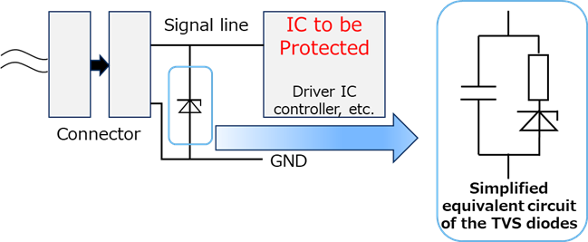
A simplified equivalent circuit of the TVS diode is shown below. When the TVS diode is off, the TVS diode acts in the same way as a capacitor by junction capacitance. This capacity is called the total capacitance CT. Since this capacitance is placed between a signal line (data path) and GND, the signal integrity of a high-speed signal is subject to degradation. To maintain signal integrity, it is necessary to select TVS diodes with adequate total capacitance CT.
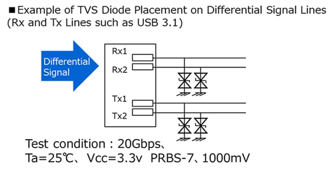
The following illustrates an example of TVS diode evaluation on a high-speed signal line.
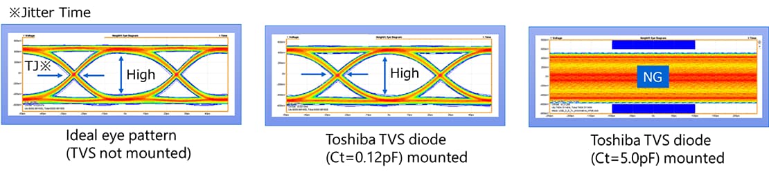
When TVS diode with a capacitance of 5.0 pF is used for a signal operating at 20 Gbps, signal waveform appears as closure of the eye pattern* , resulting in degraded signal integrity (Figure 3, right). In contrast, when using our low-capacitance TVS diode, the eye pattern remains open, enabling transmission without signal degradation (Figure 3, center). Therefore, for high-speed signal inputs, it is critical to carefully consider the capacitance value when selecting a TVS diode.
*Eye pattern: A visual representation created by superimposing multiple digital signal waveforms, making signal timing and voltage characteristics observable. It is commonly used to verify whether high-speed signals are transmitted correctly.
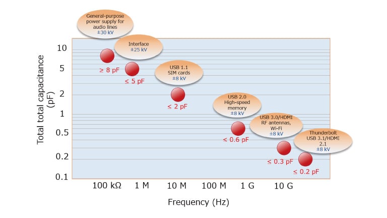
Use the following figure as a guide when selecting TVS diodes.
Related Links
There are related explanations in the following materials, so please refer to them.
FAQs
Application Notes

* The terms HDMI, and HDMI High-Definition Multimedia Interface, and the HDMI Logo are trademarks or registered trademarks of HDMI Licensing Administrator, Inc. in the United States and other countries.
* Other company names, product names, and service names may be trademarks of their respective companies.