

 : Products list (parametric search)



PFC Circuit Design with the Online Simulator
Please Login to view more detailed articles.
Click here to Login
Introduction - Why PFC Circuits Need to Be Considered in the Early Design Stage
In an AC-DC power supply, rectification and smoothing tend to concentrate the input current around the peaks of the input voltage, resulting in distortion of the input current and harmonic currents. Since harmonic currents can lead to heating of wiring and components and can affect the power line, it is important to consider countermeasures from the design stage of the primary (input) side, in addition to optimizing the downstream DC-DC stage.
A power factor correction (PFC) circuit controls the input current in synchronization with the input voltage, bringing the current waveform closer to a sinusoidal waveform to improve the power factor and reduce harmonic current. IEC 61000-3-2 specifies limits for harmonic current emissions from electrical and electronic equipment with a rated input current of 16A or less per phase connected to a public low-voltage distribution system. For this reason, a PFC circuit is an important element that should be considered at the early stage of design, not only to improve efficiency but also to ensure compliance with standards and maintain power quality.
*1: IEC 61000-3-2 (rated input current ≤16A per phase), IEC 61000-3-12 (rated input current >16A to ≤75A per phase), etc.
In an AC-DC power supply, distortion of the input current causes heating of wiring and components and injects harmonic currents into the power line.
Such impacts on the power line are difficult to mitigate at a later stage, even if the downstream (DC-DC) stage is optimized. Therefore, the design approach must be determined at the primary (input) stage.
In addition, harmonic current is limited by international standards*1, which define the allowable harmonic current that equipment can inject into the power line.
To address this issue, a power factor correction (PFC) circuit is used. A PFC circuit is an essential element that should be considered at the early stage of design, not only to improve efficiency but also to ensure compliance with standards.
*1: IEC 61000-3-2 (≤16A per phase), IEC 61000-3-12 (>16A to ≤75A per phase), etc.
What Does a PFC Circuit Improve?
In a conventional rectifier and smoothing circuit (bridge rectifier with a smoothing capacitor), the input current flows in pulses when the AC voltage exceeds the voltage across the smoothing capacitor, and the current waveform deviates significantly from a sinusoidal waveform. As a result, even for the same output power, the RMS value of the input current increases, causing heating of wiring and components and increasing harmonic current.
A PFC circuit uses inductors and switching devices to control the input current, making it more closely match a sinusoidal waveform that is in phase with the input voltage. As a result, the power factor is brought closer to unity and harmonic currents are reduced.
In a conventional rectifier and smoothing circuit (bridge rectifier with a smoothing capacitor), the input current flows in pulses near the peaks of the AC voltage, and the current waveform deviates from a sinusoidal waveform.
As a result, even for the same output power, the RMS value of the input current increases, causing heating of wiring and components and injecting harmonic currents into the power line.
A PFC circuit controls the input current in synchronization with the input voltage, bringing the current waveform closer to a sinusoidal waveform and reducing the phase difference between voltage and current. This improves the power factor and reduces harmonic current.
Basic Concept of Switching PFC
In modern PFC circuits, active (switching) methods using MOSFETs are widely used. A boost PFC circuit uses inductors, MOSFETs, and diodes to control the inductor current according to the instantaneous value of the input voltage. Key design considerations include the conduction mode, such as whether the inductor current flows continuously or switching occurs at the zero-current point, as well as current ripple, peak current, switching loss, and the impact on the EMI filter.
The Online Simulator is effective for preliminary verification because it allows users to observe these waveform characteristics and compare the effects of different MOSFETs and circuit parameters.
In modern PFC circuits, a switching method using MOSFETs is commonly used. An inductor and switching devices are used to control the current in accordance with variations in the input voltage.
In switching PFC, key design considerations include the switching condition of the inductor current and how the current ripple and peak current vary.
PFC Circuit Topologies
PFC topologies vary depending on the circuit configuration and control method and are selected according to the application, power level, efficiency requirements, component count, and design complexity. In the Online Simulator, the following topologies are available as the input stage (PFC stage) of an AC-DC power supply, allowing users to select a topology and verify its operation.
- Single PFC: Single-phase boost PFC (basic topology), suitable for understanding the circuit and designing small- to medium-power supplies.
- Interleaved PFC: Two-phase PFC in which each phase operates with a phase shift, enabling verification of current sharing, ripple reduction, and thermal distribution.
- Totem-Pole PFC: A topology in which MOSFETs perform both rectification and PFC operation for high efficiency.
- Semi-Bridgeless PFC: A bridgeless-type topology that balances reduced bridge losses with a simpler circuit configuration.
| Category | Topology | Key features | Typical applications/positioning |
|---|---|---|---|
| Passive | Passive PFC | Uses a reactor to suppress input current variation; simple but relatively large | Low-power and simple power supplies |
| Active | Single PFC | Single-phase boost PFC; basic topology with the simplest circuit configuration | Basis for small- to medium-power supplies |
| Interleaved PFC | Two-phase current sharing, reduced ripple, and improved thermal distribution | Medium- to high-power supplies | |
| Totem-pole PFC | Uses MOSFETs for both rectification and PFC operation to improve efficiency | High-efficiency power supplies | |
| Semi-bridgeless PFC | Partially reduces bridge loss while retaining some diodes | Applications aiming at higher efficiency with moderate complexity | |
| Bridgeless PFC | Eliminates the input bridge to reduce conduction losses | High-efficiency and high-power applications |
PFC techniques vary by circuit configuration and are selected according to application, power level, and efficiency requirements. In the Online Simulator, the following topologies are available as the input stage (PFC stage) of an AC-DC power supply.
- Single PFC: Single-phase boost PFC (basic topology)
- Interleaved PFC: Two-phase PFC (current sharing and reduced ripple)
- Totem-Pole PFC: A topology in which MOSFETs perform both rectification and PFC operation
- Semi-Bridgeless PFC: A bridgeless configuration that retains some diodes
| Category | Topology | Key features | Typical applications/positioning |
|---|---|---|---|
| Passive | Passive PFC | Uses a reactor to suppress input current variation; simple but relatively large | Low-power and simple power supplies |
| Active | Single PFC | Single-phase boost PFC; basic topology with the simplest circuit configuration | Basis for small- to medium-power supplies |
| Interleaved PFC | Two-phase current sharing, reduced ripple, and improved thermal distribution | Medium- to high-power supplies | |
| Totem-pole PFC | Uses MOSFETs for both rectification and PFC operation to improve efficiency | High-efficiency power supplies | |
| Semi-bridgeless PFC | Partially reduces bridge loss while retaining some diodes | Applications aiming at higher efficiency with moderate complexity | |
| Bridgeless PFC | Eliminates the input bridge to reduce conduction losses | High-efficiency and high-power applications |
Switching Conduction Modes (CCM/CRM/DCM)
In PFC circuits, not only the topology but also the conduction mode (how the inductor current flows) is important. The main modes include CCM (continuous conduction mode), CRM/BCM (critical/boundary conduction mode), and DCM (discontinuous conduction mode).
In CCM, current flows continuously, and ripple can be kept relatively small, making it suitable for medium- to high-power applications. In contrast, CRM/BCM switches at the zero-current point, offering advantages in terms of switching losses and diode reverse recovery, but requires consideration of current peaks and control. DCM is relatively easy to use for low-power applications, but peak currents tend to be higher and must be carefully considered. Since waveform characteristics such as ripple, peak current, and distortion directly affect design decisions, it is important to evaluate waveforms not only from the topology point of view but also from the conduction mode point of view.
| Mode | Features | Impact on design |
|---|---|---|
| CCM (Continuous Conduction Mode) | Current does not become discontinuous/small ripple | Suitable for large-capacity power supplies/switching loss design is important |
| CRM (Critical Conduction Mode) | Switching occurs when the inductor current drops to zero | Good balance between loss and efficiency |
| DCM (Discontinuous Conduction Mode) | Current becomes zero every cycle | Suitable for low-capacity power supplies/high peak current |
In PFC circuits, there are multiple options for how current is conducted. Active PFC circuits are divided into three types according to the current conduction mode used: continuous conduction mode (CCM), critical conduction mode (CRM), and discontinuous conduction mode (DCM).
In CCM, current flows continuously, enabling input current shaping.
Since waveform characteristics such as ripple, peak current, and distortion directly affect design decisions, it is important to check the waveform not only from the topology point of view but also from the conduction mode point of view.
| Mode | Features | Impact on design |
|---|---|---|
| CCM (Continuous Conduction Mode) | Current does not become discontinuous/small ripple | Suitable for large-capacity power supplies/switching loss design is important |
| CRM (Critical Conduction Mode) | Switching occurs when the inductor current drops to zero | Good balance between loss and efficiency |
| DCM (Discontinuous Conduction Mode) | Current becomes zero every cycle | Suitable for low-capacity power supplies/high peak current |
What Can Be Verified Using the Online Simulator?
The Online Simulator allows users to verify input voltage and current waveforms, output voltage and current, and inductor current, and compare the effects of different circuit topologies, MOSFETs, and circuit parameters.
In the early design stage, before actual hardware evaluation, users can verify whether the input current follows the input voltage, whether the inductor current peak and ripple are within acceptable ranges, and whether the output voltage remains stable near the target value. In addition, by using the Accurate mode, not only waveforms but also efficiency and device losses can be verified, making it useful for selecting components and refining circuit parameters during the early design stage.
The Online Simulator allows users to verify input current waveforms, differences in current ripple and peak current among circuit topologies, and operating waveforms when MOSFETs or circuit parameters are changed.
In addition, the simulator displays waveforms after setting the conditions and enables comparison of waveforms, making it effective for preliminary verification in the early design stage.
Login is required to use the circuit simulator.

Use Case Covered in This Article (Why Interleaved PFC Is Selected)
This article introduces an interleaved PFC as one example of a PFC circuit. An interleaved PFC divides a boost PFC circuit into two or more phases and operates each phase with a phase shift. In a two-phase configuration, the phases are typically driven 180° out of phase, allowing the current to be shared between the phases.
The inductor current ripples of each phase overlap, causing the ripple components to partially cancel each other at the input side. As a result, input current ripple and output capacitor ripple current can be reduced more easily, providing advantages for EMI filter design and thermal management.
Because these effects can be easily observed in the waveforms, interleaved PFC is well suited for understanding and preliminary verification using the Online Simulator.
This article introduces an interleaved PFC as one example of a PFC circuit.
An interleaved PFC divides a boost PFC circuit into two or more phases and drives each phase with a 180° phase shift. By sharing the current between phases, device stress and heat generation are reduced.
In addition, since the inductor currents of two phases overlap, their ripple currents cancel each other out, resulting in reduced overall ripple current. Furthermore, because the effective ripple frequency increases, this approach is advantageous for input and output filter design, including ripple current and EMI.
Because the effects can be intuitively understood from the waveforms, this method is suitable for understanding and preliminary verification through waveform observation using the Online Simulator.
Login is required to use the circuit simulator.
Verification Example Using the Online Simulator (Interleaved PFC)
1. Simulation Conditions
In this simulation, the conditions shown in Figure 1 are set, and verification is carried out using TK125U60Z1, which is presented as a recommended MOSFET.
- Input: Vin = 230V, Fin = 50Hz
- Output: Vout = 380V, Pout = 800W
- Switching frequency: 65kHz
- MOSFET used: TK125U60Z1
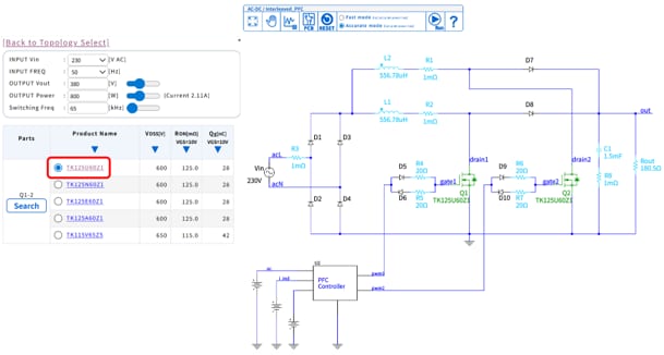
Figure1: Interleaved PFC simulation conditions and circuit configuration
2. Simulation Results
Figure 2 shows the output voltage and current, Figure 3 shows the input voltage and current, and Figure 4 shows the inductor current waveforms.
First, the output voltage waveform in Figure 2 shows that the output voltage is controlled near the target value of 380V and remains stable.
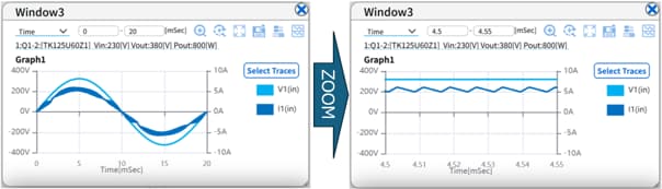
Figure2: Output voltage and output current waveforms of the Interleaved PFC
Next, the input current waveform in Figure 3 shows that the current follows the input voltage and exhibits a sinusoidal waveform. This indicates that the current waveform is corrected by the PFC circuit, and power factor correction is achieved.
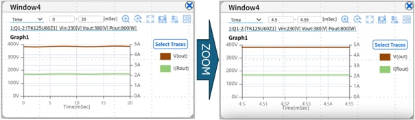
Figure3: Input voltage and input current waveforms of the Interleaved PFC
Furthermore, the inductor current waveform in Figure 4 shows that the currents of inductors L1 and L2 operate with a phase shift relative to each other, confirming interleaved operation with a 180° phase difference. This indicates that the current is shared in the two-phase configuration.
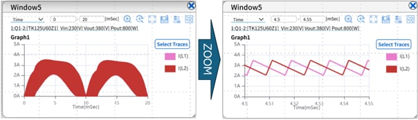
Figure4: Inductor current waveforms of the Interleaved PFC showing interleaved operation with a 180-degree phase difference
3. Efficiency and Loss Evaluation in Accurate Mode
By using the Accurate mode of the Online Simulator, not only waveforms but also efficiency and device losses can be verified.
In this simulation, the following results are obtained as shown in Figure 5.
- Efficiency: 92.2%
- Losses
o Q1: 1.29W
o Q2: 1.29W
These results indicate that:
- the two-phase configuration distributes the losses across each MOSFET;
- the losses of Q1 and Q2 are identical, indicating that each phase shares the current evenly; and
- the converter operates with an efficiency of approximately 92%, which is a reasonable result under the set conditions.
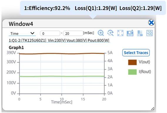
Figure5: Efficiency and loss evaluation results in Accurate mode
Specifications and Key Points of the MOSFET Used (TK125U60Z1)
The main specifications of TK125U60Z1 used in this verification are as follows.
- N-channel power MOSFET (DTMOSVI generation), package: TOLL
- Drain-source voltage VDSS = 600V
- Drain Current (DC) ID = 20A
- Drain-source on-resistance RDS(ON) = 125mΩ (Max.)
- Total gate charge Qg = 28nC (Typ.)
- Input capacitance Ciss = 1620pF (Typ.)
- Body diode characteristics (reference): Reverse recovery time trr = 285ns (Typ.), Reverse recovery charge Qrr = 3100nC (Typ.)
Product information (reference): TK125U60Z1
The main specifications of TK125U60Z1 used in this verification are as follows.
- N-channel power MOSFET (DTMOSVI generation), package: TOLL
- Drain-source voltage VDSS = 600V
- Drain current (DC) ID = 20A
- Drain-source on-resistance RDS(ON) = 125mΩ (Max.)
- Total gate charge Qg = 28nC (Typ.)
- Input capacitance Ciss = 1620pF (Typ.)
- Body diode characteristics (reference): Reverse recovery time trr = 285ns (Typ.), Reverse recovery charge Qrr = 3100nC (Typ.)
Product information (reference): TK125U60Z1
Summary
A PFC circuit reduces harmonic current by bringing the input current closer to a sinusoidal waveform synchronized with the input voltage and improves the power factor. The characteristics, such as current ripple, peak current, device stress, loss and efficiency, and design difficulty, vary depending on the selected topology (Single/Interleaved/Totem-Pole/Semi-Bridgeless) and current conduction mode (CCM/CRM/DCM).
By using the Online Simulator, waveforms can be compared while switching topologies, MOSFETs, and circuit parameters without environment setup or device model preparation. In addition, the Accurate mode enables evaluation of efficiency and device losses, helping to streamline initial design exploration and component selection.
In the Interleaved PFC example presented in this article, the following can be verified in a continuous flow:
(1) current sharing with a 180° phase shift
(2) ripple reduction
(3) input current shaping and output voltage control
(4) evaluation of efficiency and losses
The ability to verify PFC circuit operation from both waveform and numerical perspectives is a major advantage of the Online Simulator.
Trying out an Interleaved PFC
A PFC circuit reduces harmonic current by bringing the input current closer to a sinusoidal waveform and improves the power factor. The characteristics, such as current waveform, ripple, device stress, loss and efficiency, and design difficulty, vary depending on the selected topology (Single/Interleaved/Totem-Pole/Semi-Bridgeless) and current conduction mode (CCM/CRM/DCM).
By using the Online Simulator, waveforms can be compared while switching topologies, MOSFETs, and circuit parameters without environment setup or device model preparation. In addition, by using the Accurate mode, efficiency and device losses (e.g., Q1/Q2) can be evaluated, enabling quick initial design exploration.
In the interleaved PFC example presented in this article, the following can be verified in a continuous flow:
(1) current sharing with a 180° phase shift,
(2) ripple reduction,
(3) input current shaping and output voltage control, and
(4) evaluation of efficiency and losses.
Trying out an Interleaved PFC
Login is required to use the circuit simulator.
Related Contents
Application note: Power Factor Correction (PFC) Circuits (PDF: 1.38MB)
Highlighted Contents: The Online Circuit Simulator eliminates the need for special software