

- General Top
- SEMICONDUCTOR
- STORAGE
- COMPANY
-
My ToshibaSemicon
- Semiconductor Top
-
ApplicationsAutomotive
Body Electronics
xEV
In-Vehicle Infotainment
Advanced Driver-Assistance Systems (ADAS)
Chassis
IndustrialInfrastructure
BEMS/HEMS
Factory Automation
Commercial Equipment
Consumer/PersonalIoT Equipment
Healthcare
Wearable Device
Mobile
Computer Peripherals
-
ProductsAutomotive Devices
Discrete Semiconductor
Diodes
Transistors
Logic ICs
Analog Devices
- Automotive SmartMCD™ (Integreted SoC Conbining Microcontroller and Driver)
- Automotive Brushless Motor Driver ICs
- Automotive Brushed DC Motor Driver ICs
- Automotive Stepping Motor Driver ICs
- Automotive Driver ICs
- Automotive System Power Supplies ICs
- Automotive audio power amplifier ICs
- Automotive Network Communication
Digital Devices
Wireless Devices
※
 : Products list (parametric search)Power Semiconductors
SiC Power Devices
※
: Products list (parametric search)Isolators/Solid State RelaysPhotocouplers
Digital Isolators
Solid State Relays
Fiber Optic Transmitting Modules
※
: Products list (parametric search)MOSFETsIGBTs/IEGTsBipolar Transistors※
: Products list (parametric search)Diodes※
: Products list (parametric search)MicrocontrollersMotor Driver ICsIntelligent Power ICs※
: Products list (parametric search)Power Management ICsLinear ICs※
: Products list (parametric search)General Purpose Logic ICsLinear Image SensorsOther Product ICsOther Product ICs
※
: Products list (parametric search) -
Design & Development
-
Knowledge
- Where To Buy



- Part Number & Keyword Search
- Cross Reference Search
- Parametric Search
- Stock Check & Purchase
This webpage doesn't work with Internet Explorer. Please use the latest version of Google Chrome, Microsoft Edge, Mozilla Firefox or Safari.
require 3 characters or more. Search for multiple part numbers fromhere.
The information presented in this cross reference is based on TOSHIBA's selection criteria and should be treated as a suggestion only. Please carefully review the latest versions of all relevant information on the TOSHIBA products, including without limitation data sheets and validate all operating parameters of the TOSHIBA products to ensure that the suggested TOSHIBA products are truly compatible with your design and application.Please note that this cross reference is based on TOSHIBA's estimate of compatibility with other manufacturers' products, based on other manufacturers' published data, at the time the data was collected.TOSHIBA is not responsible for any incorrect or incomplete information. Information is subject to change at any time without notice.
require 3 characters or more.
40V/2A Stepping Motor Driver IC with Phase Interface Resistant to External Noise for Industrial Applications
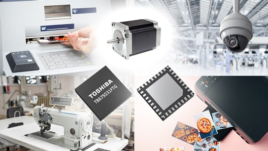
Toshiba Electronic Devices & Storage Corporation ("Toshiba") has launched the "TB67S531FTG", a constant-current, two-phase bipolar stepping motor driver IC for industrial equipment such as sewing machines and photo printers. The new product features a motor output voltage rating of 40 V and an output current rating of 2.0A[1], and employs a phase interface for motor control inputs.
The new product is a derivative product based on the existing TB67S539FTG. With the clock input method used in TB67S539FTG, the current steps[2] for each phase are stepped forward on the rising edge of the clock, offering the advantage of easy step management. On the other hand, due to the influence of noise, the current steps may unintentionally progress, causing malfunctions that can lead to step-out. The TB67S531FTG adopts a phase input method that directly controls the output current of each phase. As a result, even if instantaneous noise occurs, unintended transitions of the current steps are less likely, suppressing motor step-out caused by noise and making the product well suited for applications such as sewing machines and photo printers, where stable operation is required even in noisy environments.
In addition, the new product reduces heat generation by lowering the On-resistance (upper + lower) between the drain and source of the output transistors to 0.8Ω (typ.). The product also integrates a current detection circuit for constant-current motor control, eliminating the need for an external current detection resistor. Furthermore, it integrates the charge pump circuit for output stage control required for the H-bridge circuit[3] with N-channel/N-channel configuration[4], eliminating the need for an external charge pump capacitor. The product is housed in a small QFN32 package (5×5mm), contributing to a reduced component count and smaller mounting area.
Toshiba will continue to expand its product lineup to support diverse applications, helping to reduce users’ design burden, save PCB space, and deliver value that contributes to improved development efficiency.
Notes:
[1] Actual driven motor current depends on the use environment and such factors as ambient temperature and power supply voltage.
[2] A stepping motor controls the electrical angle in discrete steps, meaning that the current setting values for each phase are switched according to the corresponding electrical angle.
[3] This circuit configuration is named after its output circuit shape, which resembles the letter "H." It controls the direction and path of the current flowing through each phase coil of the stepper motor and regulates the coil current to a specified value.
[4] Output-stage configuration that uses N-channel MOSFETs in both the upper and lower stages (although it is common for the upper stage to use P-channel MOSFET and the lower stage to use N-channel MOSFET)
Features
- Phase interface method that is resistant to step-out caused by external noise
- No external current detection resistor required for constant-current control (Built-in)
- No external charge pump capacitor required (Built-in)
Applications
- Sewing machines
- Photo printers
- Printers
- Financial terminals (such as ATMs)
- Surveillance cameras
- Scanners, etc.
Main Specifications
(Unless otherwise specified, Ta=25°C)
| Part number | TB67S531FTG | TB67S539FTG[5] | |||
|---|---|---|---|---|---|
| Supported motor | Two-phase bipolar stepping motor | ||||
| Interface | Phase | Clock | |||
| Absolute maximum ratings | Motor output voltage VOUT (V) | 40 | |||
| Motor output current IOUT (A) | 2.0 | ||||
| Operating temperature Topr (°C) | -40 to 85 | ||||
| Operating ranges | Motor power supply voltage VM (V) | 4.5 to 33 | |||
| Motor output current IOUT (A) | Max | 1.8 | |||
| Electrical characteristics |
Output transistor between drain and source On resistance (upper + lower) RON(D-S) (Ω) |
Tj=25°C, IOUT=2.0A |
Typ. | 0.8 | |
| Resistor for current detection | Not required | ||||
| Capacitor for charge pump | Not required | ||||
| Excitation mode | Full step to quarter step | Full step to 1/32 step | |||
| Decay setting function | Selectable (Mixed / Slow / Fast / ADMD[6]) | ||||
| Torque function | Switchable set current without external components |
Switchable set current without external components (4 modes: 100%, 75%, 50%, 25%) |
|||
| Abnormality detection function | Over-current detection (ISD), thermal shutdown (TSD), under voltage lockout (UVLO) (With error flag output) |
||||
| Package | Name | P-VQFN32-0505-0.50-008 | P-VQFN32-0505-0.50-004 | ||
| Size (mm) | Typ. | 5×5 | |||
| Sample Check & availability |
|
 |
|||
Notes:
[5] Existing product
[6] Abbreviation of Advanced Dynamic Mixed Decay, Toshiba's original technique for improving waveform qualities at high speed.
Queries about purchasing, sampling and IC reliability
Stock Check & Purchase
require 3 characters or more.
Through this website you are able to proceed to the website of our distributors ("Third Party Website") which is not under the control of Toshiba Corporation and its subsidiaries and affiliates (collectively "Toshiba"). The Third Party Website is made available to you as a convenience only and you agree to use the Third Party Website at your own risk. The link of the Third Party Website does not necessarily imply a recommendation or an endorsement by Toshiba of the Third Party Website. Please be aware that Toshiba is not responsible for any transaction done through the Third Party Website, and such transactions shall be subject to terms and conditions which may be provided in the Third Party Website.
* Company names, product names, and service names may be trademarks of their respective companies.
* Information in this document, including product prices and specifications, content of services and contact information, is current on the date of the announcement but is subject to change without prior notice.