

- General Top
- SEMICONDUCTOR
- STORAGE
- COMPANY
-
My ToshibaSemicon
- Semiconductor Top
-
ApplicationsAutomotive
Body Electronics
xEV
In-Vehicle Infotainment
Advanced Driver-Assistance Systems (ADAS)
Chassis
IndustrialInfrastructure
BEMS/HEMS
Factory Automation
Commercial Equipment
Consumer/PersonalIoT Equipment
Healthcare
Wearable Device
Mobile
Computer Peripherals
-
ProductsAutomotive Devices
Discrete Semiconductor
Diodes
Transistors
Logic ICs
Analog Devices
- Automotive SmartMCD™ (Integreted SoC Conbining Microcontroller and Driver)
- Automotive Brushless Motor Driver ICs
- Automotive Brushed DC Motor Driver ICs
- Automotive Stepping Motor Driver ICs
- Automotive Driver ICs
- Automotive System Power Supplies ICs
- Automotive audio power amplifier ICs
- Automotive Network Communication
Digital Devices
Wireless Devices
※
 : Products list (parametric search)Power Semiconductors
SiC Power Devices
※
: Products list (parametric search)Isolators/Solid State RelaysPhotocouplers
Digital Isolators
Solid State Relays
Fiber Optic Transmitting Modules
※
: Products list (parametric search)MOSFETsIGBTs/IEGTsBipolar Transistors※
: Products list (parametric search)Diodes※
: Products list (parametric search)MicrocontrollersMotor Driver ICsIntelligent Power ICs※
: Products list (parametric search)Power Management ICsLinear ICs※
: Products list (parametric search)General Purpose Logic ICsLinear Image SensorsOther Product ICsOther Product ICs
※
: Products list (parametric search) -
Design & Development
-
Knowledge
- Where To Buy



- Part Number & Keyword Search
- Cross Reference Search
- Parametric Search
- Stock Check & Purchase
This webpage doesn't work with Internet Explorer. Please use the latest version of Google Chrome, Microsoft Edge, Mozilla Firefox or Safari.
require 3 characters or more. Search for multiple part numbers fromhere.
The information presented in this cross reference is based on TOSHIBA's selection criteria and should be treated as a suggestion only. Please carefully review the latest versions of all relevant information on the TOSHIBA products, including without limitation data sheets and validate all operating parameters of the TOSHIBA products to ensure that the suggested TOSHIBA products are truly compatible with your design and application.Please note that this cross reference is based on TOSHIBA's estimate of compatibility with other manufacturers' products, based on other manufacturers' published data, at the time the data was collected.TOSHIBA is not responsible for any incorrect or incomplete information. Information is subject to change at any time without notice.
require 3 characters or more.
500mA LDO Regulators in SOT-25 Package that Help Stabilize Power Supply Lines with Low Noise and Fast Load Transient Response
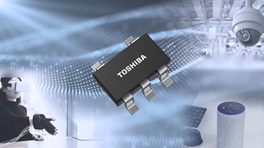
Toshiba Electronic Devices & Storage Corporation ("Toshiba") has launched 35 products in the TCR5FF series of LDO regulators for consumer equipment such as security cameras, AR/VR devices, and IoT equipment, and industrial equipment including industrial cameras, high-precision sensors, and measurement instruments. Featuring low-noise characteristics and fast load transient response, the series helps stabilize power supply lines. The regulators adopt a highly mountable SOT-25 package, facilitating stable power supply to noise-sensitive circuits.
In recent years, driven by advances in IoT and AI technologies, electronic equipment has achieved higher sensor accuracy, more sophisticated image processing, and faster, higher-capacity communications. CMOS image sensors, RF circuits, and various sensors that support these functions are highly sensitive to power supply noise, increasing the importance of stable, low-noise power supplies. In addition, growing demand for energy efficiency has led to more applications that frequently switch between standby and high-speed operation. Such operating conditions can cause sudden load current fluctuations and instability in power supply lines, creating demand for LDO regulators that suppress noise while maintaining stable output voltage during load transients.
The new TCR5FF series improves load transient response from standby by approximately 80%[1] compared with Toshiba’s existing TCR3RM series. This helps suppress output voltage fluctuations during sudden load changes and contributes to the stable operation of downstream circuits. In addition, by combining a bandgap circuit, a low-pass filter[2], and a high-speed, low-noise operational amplifier, the series achieves an industry-leading[3] ripple rejection ratio[4] of 91dB (typ.)[5] together with low output noise voltage. These features improve noise rejection performance and enable stable, low-noise voltage supply.
The TCR5FF series delivers the same level of power supply performance as the TCR5FM series, which offers low-noise performance and fast load transient response, while adopting an easy-to-mount SOT‑25 package. The package's lead terminals facilitate mounting and allow easy visual inspection after assembly, making the regulators suitable for a wide range of consumer and industrial applications.
The series supports a maximum output current of 500mA and an operating temperature range of -40 to 125°C. The lineup includes 35 products with output voltages ranging from 0.9V to 5.0V, enabling selection according to application requirements.
Toshiba will continue to advance product development that contributes to higher performance and stable operation of electronic equipment.
Notes:
[1] Values measured by Toshiba. Test condition: VIN=3.3V, VOUT=2.8V, IOUT=0mA ↔ 100mA, tr=1.0μs, tf=1.0μs, Ta=25°C
[2] A filter that allows only low‑frequency components to pass through while blocking high‑frequency components.
[3] Among LDO regulators with a maximum output of 500mA, Toshiba surveyed as of October 2026.
[4] Ripple rejection ratio, also referred to as PSRR (Power Supply Rejection Ratio), is a quantitative index that indicates how much ripple voltage component (noise) superimposed on the input voltage is transmitted to the output voltage. It is expressed as the ratio between the input ripple voltage and the resulting output ripple voltage.
[5] Values measured by Toshiba. Test condition: CIN=none, COUT=1.0μF, VIN=3.3V, VOUT=2.8V, VIN Ripple=200mVp-p, IOUT=10mA, Ta=25°C
Features
- Fast load transient response: ΔVOUT=−75/+25mV (typ.) (IOUT=0mA ↔ 100mA, VOUT=2.8V)
- High ripple rejection ratio: R.R.=91dB (typ.) (f=1kHz, VOUT=2.8V)
- Low output noise voltage: VNO=5μVrms (typ.) (10Hz≤f≤100kHz)
Features Explanation
1. Fast load transient response: ΔVOUT=−75/+25mV (typ.) (IOUT=0mA ↔ 100mA, VOUT=2.8V)
The TCR5FF series offers fast and excellent load transient response to sudden load changes. Compared to Toshiba’s existing TCR3RM series, the response from no‑load conditions has improved by approximately 80%[1], and during load transitions between 0mA and 100mA at a 2.8V output, the typical voltage variation is limited to -75mV/+25mV. It also delivers excellent load transient response under loaded conditions, with the typical voltage variation limited to −60mV/+40mV during load transitions between 1mA and 500mA at a 2.8V output. This contributes to the stable operation of downstream circuits.
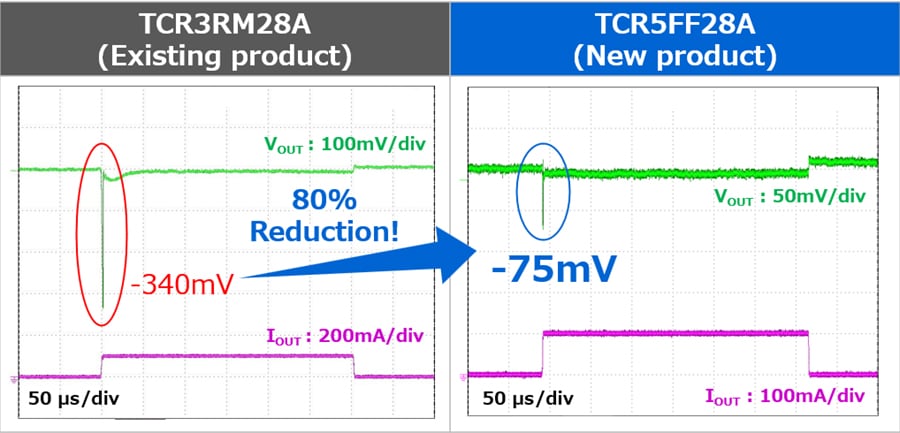
Figure 1. Comparison of Load Transient Response Characteristics between Existing and New Products
(VIN=3.3V, VOUT=2.8V, IOUT=0mA ↔ 100mA, tr=1.0μs, tf=1.0μs, Ta=25°C)
2. High ripple rejection ratio: R.R.=91dB (typ.) (f=1kHz, VOUT=2.8V)
The ripple rejection ratio indicates the ratio between the input ripple voltage and the resulting output ripple voltage. The TCR5FF series achieves a high ripple rejection ratio by combining a bandgap circuit, a low‑pass filter[2], and a high‑speed, low‑noise operational amplifier. At a 3.3V input and 2.8V output, the ripple rejection ratio is 91dB (typ.) at f=1kHz[5]. This helps reduce noise transmitted from the input side in power supply lines for circuit downstream of switching power supplies and noise-sensitive circuits.
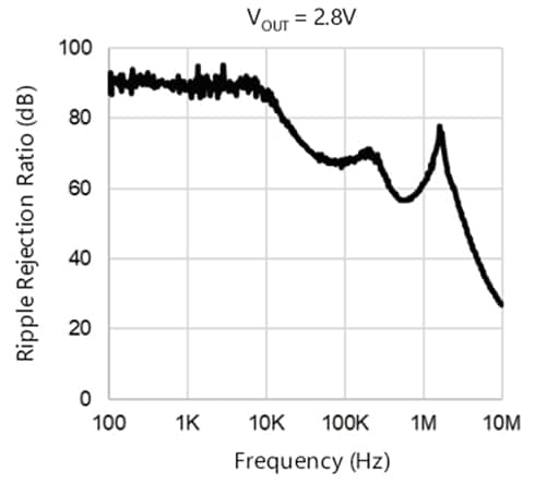
Figure 2. Ripple Rejection Ratio vs. Frequency
(CIN=none, COUT=1.0μF, VIN=3.3V, VOUT=2.8V, VIN Ripple=200mVp-p, IOUT=10mA, Ta=25°C)
3. Low output noise voltage: VNO=5μVrms (typ.) (10Hz≤f≤100kHz)
Output noise voltage refers to the integrated value of noise contained in the output voltage of the LDO. The TCR5FF series achieves an output noise voltage of 5μVrms (typ.) (10Hz≤f≤100kHz) at a 3.3V input and 2.8V output. By providing a low-noise power supply, the series helps ensure the performance of noise-sensitive circuits, including CMOS image sensors, RF circuits, and various sensors.
The series is suitable for applications that require low power supply noise and stable output voltage, such as high‑sensitivity analog circuits, RF circuits, CMOS image sensors, and power supplies for sensors.
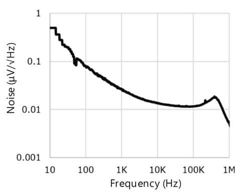
Figure 3. Output Noise Characteristics vs. Frequency
(CIN=1.0μF, COUT=1.0μF, VIN=3.3V, VOUT=2.8V, IOUT=10mA, Ta=25°C)
Applications
- Industrial equipment (industrial cameras, high‑precision sensors, measurement equipment, wireless communication equipment, IoT devices, etc.)
- Consumer equipment (security cameras, AR/VR devices, IoT devices, etc.)
Main Specifications
| Part number | TCR5FF series | ||
|---|---|---|---|
| Package | Name | SOT-25 (SMV) | |
| Size (mm) | Typ. | 2.9×2.8, t=1.1 | |
| Operating range (Topr=-40 to 125°C) |
Output current IOUT (mA) | 500 | |
| Input voltage VIN (V) | 1.55 to 5.5[6] | ||
| Output voltage VOUT (V) | 0.9 to 5.0 | ||
| Electrical characteristics (Unless otherwise specified, Tj=25°C) |
Quiescent current IB(ON) (µA) IOUT=0mA[7] |
Typ. | 10 |
| Max | 20[8] | ||
| Drop-out voltage VDO (mV)[9] IOUT=500mA, VOUT=2.8V |
Typ. | 220 | |
| Max | 337[8] | ||
| Load transient response ⊿VOUT (mV) IOUT=1mA ↔ 500mA, VOUT=2.8V |
Typ. | -60/+40 | |
| Load transient response ⊿VOUT (mV) IOUT=0mA ↔ 100mA, VOUT=2.8V |
Typ. | -75/+25 | |
| Ripple rejection ratio R.R. (dB) f=1kHz, IOUT=10mA, VOUT=2.8V |
Typ. | 91 | |
| Output noise voltage VNO (µVrms) VOUT=2.8V, IOUT=10mA, 10Hz≤f≤100kHz |
Typ. | 5 | |
| Control pin voltage (HIGH) VCTH (V) | Min | 0.79[8] | |
| Control pin voltage (LOW) VCTL (V) | Max | 0.4[8] | |
| Sample check & availability |  |
||
Notes:
[6] Please refer to the dropout voltage table for each output voltage listed in the datasheet and use within the absolute maximum junction temperature and operating temperature ranges.
[7] Control terminal current (ICT) is not included.
[8] Tj=-40 to 125°C
[9] VDO=VIN1-(VOUT1×0.97)
VOUT1 is the output voltage when VIN=VOUT+0.5V.
VIN1 is the input voltage at which the output voltage becomes 97% of VOUT1 after gradually decreasing the input voltage.
Related Contents
Product information
Low-Dropout Regulators
Technical articles
LDO Regulators: Noise reduction due to high ripple rejection ratio
LDO Regulators: Fast load transient response performance
LDO Regulators: Reduction of power consumption by low dropout voltage
Application notes
Basics of Low-Dropout (LDO) Regulator ICs (PDF: 1.3MB)
Concept of self-heating of LDOs and selection guide (PDF: 766KB)
Load Transient Response of LDO and Methods to Improve it (PDF: 1.1MB)
Simple Guide to Improving Ripple Rejection Ratio of LDO Regulators (PDF: 1.2MB)
Application examples of LDO regulators with high ripple rejection and fast load transient response (PDF: 684KB)
Applications
IoT Sensor
Surveillance Camera
Solid State Drive
Queries about purchasing, sampling and IC reliability
Stock Check & Purchase
require 3 characters or more.
Through this website you are able to proceed to the website of our distributors ("Third Party Website") which is not under the control of Toshiba Corporation and its subsidiaries and affiliates (collectively "Toshiba"). The Third Party Website is made available to you as a convenience only and you agree to use the Third Party Website at your own risk. The link of the Third Party Website does not necessarily imply a recommendation or an endorsement by Toshiba of the Third Party Website. Please be aware that Toshiba is not responsible for any transaction done through the Third Party Website, and such transactions shall be subject to terms and conditions which may be provided in the Third Party Website.
* Company names, product names, and service names may be trademarks of their respective companies.
* Information in this document, including product prices and specifications, content of services and contact information, is current on the date of the announcement but is subject to change without prior notice.