- General Top
- SEMICONDUCTOR
- STORAGE
- COMPANY
-
My ToshibaSemicon
- Semiconductor Top
-
ApplicationsAutomotive
Body Electronics
xEV
In-Vehicle Infotainment
Advanced Driver-Assistance Systems (ADAS)
Chassis
IndustrialInfrastructure
BEMS/HEMS
Factory Automation
Commercial Equipment
Consumer/PersonalIoT Equipment
Healthcare
Wearable Device
Mobile
Computer Peripherals
-
ProductsAutomotive Devices
Discrete Semiconductor
Diodes
Transistors
Logic ICs
Analog Devices
- Automotive SmartMCD™ (Integreted SoC Conbining Microcontroller and Driver)
- Automotive Brushless Motor Driver ICs
- Automotive Brushed DC Motor Driver ICs
- Automotive Stepping Motor Driver ICs
- Automotive Driver ICs
- Automotive System Power Supplies ICs
- Automotive audio power amplifier ICs
- Automotive Network Communication
Digital Devices
Wireless Devices
※
 : Products list (parametric search)Power Semiconductors
SiC Power Devices
※
: Products list (parametric search)Isolators/Solid State RelaysPhotocouplers
Digital Isolators
Solid State Relays
Fiber Optic Transmitting Modules
※
: Products list (parametric search)MOSFETsIGBTs/IEGTsBipolar Transistors※
: Products list (parametric search)Diodes※
: Products list (parametric search)MicrocontrollersMotor Driver ICsIntelligent Power ICs※
: Products list (parametric search)Power Management ICsLinear ICs※
: Products list (parametric search)General Purpose Logic ICsLinear Image SensorsOther Product ICsOther Product ICs
※
: Products list (parametric search) -
Design & Development
Design & Development
Innovation Centre
At the Toshiba Innovation Centre we constantly strive to inspire you with our technologies and solutions. Discover how to place us at the heart of your innovations.
-
Knowledge
Knowledge
Highlighted Topics
Further Materials
Other
- Where To Buy




- Part Number & Keyword Search
- Cross Reference Search
- Parametric Search
- Stock Check & Purchase
This webpage doesn't work with Internet Explorer. Please use the latest version of Google Chrome, Microsoft Edge, Mozilla Firefox or Safari.
require 3 characters or more. Search for multiple part numbers fromhere.
The information presented in this cross reference is based on TOSHIBA's selection criteria and should be treated as a suggestion only. Please carefully review the latest versions of all relevant information on the TOSHIBA products, including without limitation data sheets and validate all operating parameters of the TOSHIBA products to ensure that the suggested TOSHIBA products are truly compatible with your design and application.Please note that this cross reference is based on TOSHIBA's estimate of compatibility with other manufacturers' products, based on other manufacturers' published data, at the time the data was collected.TOSHIBA is not responsible for any incorrect or incomplete information. Information is subject to change at any time without notice.
require 3 characters or more.
How can a 3kW AC/DC converter increase power without increasing PSU volume?
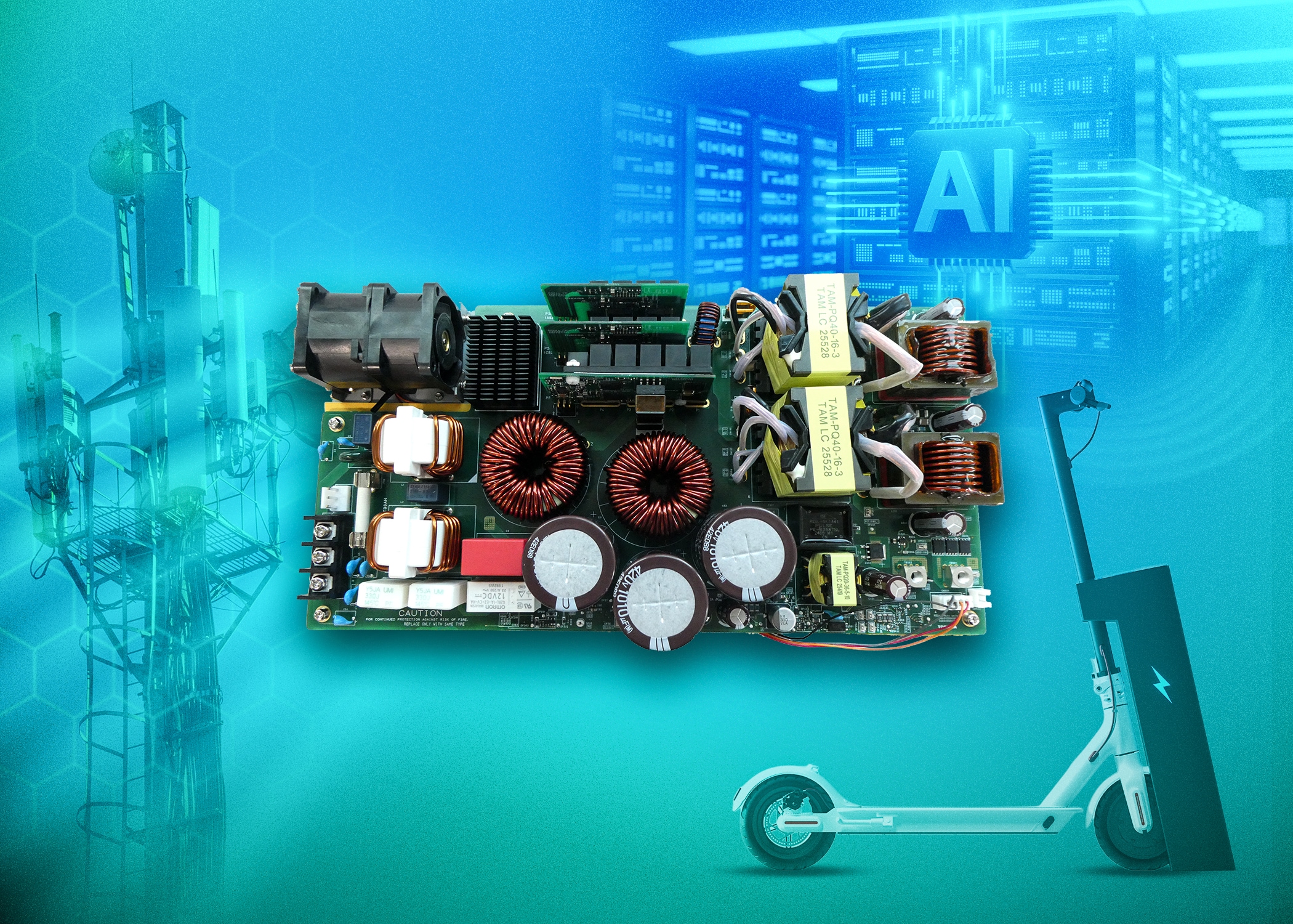
AI server racks need more power at the point of load, but the power supply cannot keep taking more space from compute hardware. Once large passive components and heatsinks define the converter envelope, higher power output becomes as much a packaging problem as an electrical one.
- Planar printed circuit board (PCB) layouts can limit power density even when the switching devices can support higher power output.
- Moving selected switching stages onto daughterboards changes how the converter uses available volume.
- Surface-mount silicon carbide (SiC) packages make that layout practical, but only when thermal paths are designed around them.
- Toshiba’s whitepaper shows how a 3kW AC/DC reference design achieved higher density through packaging, layout and thermal engineering.
Rack power demand is exposing layout limits
A conventional high-power AC/DC converter often starts with a single PCB. Transformers, capacitors and heatsinks then dictate the volume around it.
That arrangement works until the application needs several kilowatts from almost the same space. In an AI server, adding PSU volume competes directly with processors, memory and airflow. A more efficient switching device helps, but it does not automatically solve the mechanical constraint.
The design challenge moves from topology to volume
The design question becomes where each circuit section should physically sit.
Keeping all components on one board simplifies the layout, but it leaves little room to increase output power without increasing footprint. Moving switching circuitry onto vertical daughterboards can free up board area, but only if the packages, heatsinks and airflow path remain low enough to avoid creating a larger structure elsewhere.
Toshiba’s reference design uses SiC packaging to enable a multi-board layout
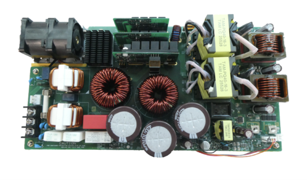
Toshiba’s 3kW AC/DC reference design separates key power-factor correction (PFC) and phase-shifted full-bridge (PSFB) switching functions onto daughterboards while larger passive components remain on the main PCB.
The design uses surface-mount SiC devices to keep those daughterboards compact and thermally manageable. Heatsinks mounted behind the switching devices provide a defined thermal path.
The result is a multi-board converter architecture that increases output power from an earlier 1.6kW design to 3kW with a 34% improvement in power density (Figure 1).
The whitepaper shows the design decisions behind the result
The full Toshiba whitepaper explains how the converter combines semi-bridgeless PFC, a PSFB stage, surface-mount SiC packaging and PCB partitioning. It also shows where thermal optimisation affected the final design.
Download the whitepaper to see how Toshiba approached higher power density through converter architecture, packaging and thermal design.