- 半導體首頁
-
應用Automotive
Body Electronics
xEV
In-Vehicle Infotainment
Advanced Driver-Assistance Systems (ADAS)
Chassis
IndustrialInfrastructure
BEMS/HEMS
Factory Automation
Commercial Equipment
Consumer/PersonalIoT Equipment
Healthcare
Wearable Device
Mobile
Computer Peripherals
-
產品車用元件
Discrete Semiconductor
Diodes
電晶體
通用邏輯IC
Analog Devices
Digital Devices
Wireless Devices
※
 : Products list (parametric search)功率半導體
※
: Products list (parametric search)隔離器/固態繼電器Photocouplers
Digital Isolators
※
: Products list (parametric search)MOSFETsIGBTs/IEGTs雙極性電晶體※
: Products list (parametric search)Diodes※
: Products list (parametric search)微控制器馬達驅動 ICs智能功率 ICs※
: Products list (parametric search)電源管理 ICs線性 ICs※
: Products list (parametric search)通用邏輯 ICs線性影像感測器其他產品其他產品
※
: Products list (parametric search) -
開發/設計支援
開發 / 設計支援
-
技術知識
- 購買管道


- 型號 & 關鍵字搜尋
- 交叉搜尋
- 參數搜尋
- 線上庫存查詢跟購買
This webpage doesn't work with Internet Explorer. Please use the latest version of Google Chrome, Microsoft Edge, Mozilla Firefox or Safari.
型號需要超過三個文字以上 Search for multiple part numbers fromhere.
The information presented in this cross reference is based on TOSHIBA's selection criteria and should be treated as a suggestion only. Please carefully review the latest versions of all relevant information on the TOSHIBA products, including without limitation data sheets and validate all operating parameters of the TOSHIBA products to ensure that the suggested TOSHIBA products are truly compatible with your design and application.Please note that this cross reference is based on TOSHIBA's estimate of compatibility with other manufacturers' products, based on other manufacturers' published data, at the time the data was collected.TOSHIBA is not responsible for any incorrect or incomplete information. Information is subject to change at any time without notice.
型號需要超過三個文字以上
Basic idea of how to calculate the base current and input voltage of a bias resistor built-in transistor (BRT)
BRTs are generally used as switches. Ideally, their on-state voltage (collector-emitter voltage, VCE) should be as close to zero as possible.
The base current should be considered to achieve this condition.
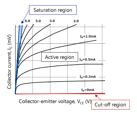
To minimize VCE, BRTs are used in the saturation region shown in Figure 1. Typically, bipolar transistors are considered to provide an hFE of 100. However, since BRTs operate in the saturation region, it is necessary to assume that they provide an hFE of 10 to 20. This means that the base current should be 1/10th to 1/20th of the collector current.
Suppose that we need a VCE of 0.2 V and an IC of 10 mA. Here, the RN1402 (with R1=R2=10 kΩ) is used as a BRT. Look at the VCE(sat) – IC curves shown in the RN1402 datasheet (Figure 3). When hFE=IC / IB=20, VCE(sat) can be read as 0.05 V to 0.06 V at IC=10 mA. So, let’s assume these conditions.
The internal base current (Ib) of the basic BRT circuit shown in Figure 2 is:
Ib= IC / hFE = 10 mA / 20 = 0.5 mA
For the sake of simplicity, assume that the internal base voltage (Vbe) is equal to the commonly used value of 0.7 V. Then, IR2 flowing through R2 is calculated as follows:
IR2 = 0.7 V / 10 kΩ = 0.07 mA
Therefore, the center value of the BRT’s base current (IB) is:
IB = Ib + IR2 = 0.57 mA
The input voltage (VI) that provides an IB of 0.57 mA is calculated as follows:
VI = R1 * IB + Vbe = 10 kΩ * 0.57 mA + 0.7 = 6.4 V
It can therefore be considered that a VCE of 0.2 V and an IC of 10 mA can be obtained by applying an input voltage of 6.4 V or higher, although it is necessary to take device variations and temperature characteristics into consideration.
In practice, an input voltage (VI) higher than 6.4 V should be applied to the B terminal. The following paragraphs describe the operation of the BRT when VI > 6.4 V.
| Characteristic | Symbol | Test Circuit | Test Condition | Min | Typ. | Max | Unit | |
|---|---|---|---|---|---|---|---|---|
Collector-emitter saturation voltage |
RN1401 to 1406 | VCE(sat) | — | IC = 5 mA, IB = 0.25mA |
— | 0.1 | 0.3 | V |
It is OK to apply a voltage higher than 6.4 V to the B terminal. Increasing the input voltage only brings the BRT into deeper saturation (i.e., decreases VCE(sat)). This causes the base-emitter voltage of the internal transistor to increase slightly, but not significantly. (For your reference, Figure 4 shows the VBE(sat)-IC curve (hFE=10) of the 2SC2712 that is equivalent to the internal transistor of the RN1402.) The base-emitter voltage varies only by several hundreds of millivolts in the collector current (IC) range in which BRTs are commonly used.
Since the base voltage hardly changes, an increase in the input voltage causes the voltage across R1 to increase, leading to an increase in the base current (ib). Saturation collector current, which is determined by load resistance and other external factors, hardly changes. Since only the base current increases, the hFE of the internal transistor decreases, causing the saturation level to increase (i.e., VCE(sat) to decrease).
Note that an increase in the saturation level might cause the time required to turn off the transistor to increase.
The maximum value is specified for the input voltage (VI). Also see the following FAQ entry.