
- 半導體首頁
-
應用Automotive
Body Electronics
xEV
In-Vehicle Infotainment
Advanced Driver-Assistance Systems (ADAS)
Chassis
IndustrialInfrastructure
BEMS/HEMS
Factory Automation
Commercial Equipment
Consumer/PersonalIoT Equipment
Healthcare
Wearable Device
Mobile
Computer Peripherals
-
產品車用元件
Discrete Semiconductor
Diodes
電晶體
通用邏輯IC
Analog Devices
Digital Devices
Wireless Devices
※
 : Products list (parametric search)功率半導體
※
: Products list (parametric search)隔離器/固態繼電器Photocouplers
Digital Isolators
※
: Products list (parametric search)MOSFETsIGBTs/IEGTs雙極性電晶體※
: Products list (parametric search)Diodes※
: Products list (parametric search)微控制器馬達驅動 ICs智能功率 ICs※
: Products list (parametric search)電源管理 ICs線性 ICs※
: Products list (parametric search)通用邏輯 ICs線性影像感測器其他產品其他產品
※
: Products list (parametric search) -
開發/設計支援
開發 / 設計支援
-
技術知識
- 購買管道


- 型號 & 關鍵字搜尋
- 交叉搜尋
- 參數搜尋
- 線上庫存查詢跟購買
This webpage doesn't work with Internet Explorer. Please use the latest version of Google Chrome, Microsoft Edge, Mozilla Firefox or Safari.
型號需要超過三個文字以上 Search for multiple part numbers fromhere.
The information presented in this cross reference is based on TOSHIBA's selection criteria and should be treated as a suggestion only. Please carefully review the latest versions of all relevant information on the TOSHIBA products, including without limitation data sheets and validate all operating parameters of the TOSHIBA products to ensure that the suggested TOSHIBA products are truly compatible with your design and application.Please note that this cross reference is based on TOSHIBA's estimate of compatibility with other manufacturers' products, based on other manufacturers' published data, at the time the data was collected.TOSHIBA is not responsible for any incorrect or incomplete information. Information is subject to change at any time without notice.
型號需要超過三個文字以上
How to select bias resistor built-in transistors (BRTs)

Typically, bias resistor built-in transistors (BRTs) are used as switches. Therefore, let’s assume the use of BRTs as switches.
As a switch, use an NPN transistor when the control signal has positive logic and a PNP transistor when the control signal has negative logic. Considerations for BRTs include the following:
- Logic polarity of the control signal (NPN/PNP)
- Turning on and off the transistor without fail via a control signal (VI(ON) and VI(OFF) voltages)
- Obtaining necessary voltage when the transistor is on (i.e., reducing a collector-emitter voltage drop in the “on” state)
- Reducing the turn-on or turn-off time (i.e., increasing the switching speed)
These considerations are explained below using the basic circuit with an NPN BRT shown in Figure 1. The BRT is enclosed in the dashed box. VI is a control signal, VCC is a power supply, and RL is a load, including a pull-up resistor.
1.Transistor’s polarity (NPN/PNP)
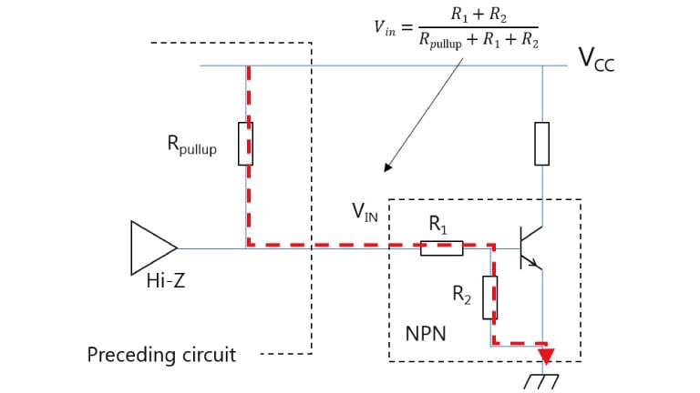
Select either an NPN or PNP BRT according to the logic of the preceding circuit. Use an NPN BRT if the output of the preceding circuit can assume the High-Z state and is pulled down to the GND level when it is in the High-Z state. Use a PNP BRT if the output of the preceding circuit is pulled up to the VCC level. When the output of the preceding circuit is in the High-Z state, a BRT might malfunction at the midpoint potential between the pull-up resistor and the built-in bias resistors.
You can use both PNP and NPN BRTs when the preceding circuit has neither a pull-up nor pull-down resistor. In this case, select a PNP or NPN BRT according to the specification of the following circuit.
(For example, select an NPN transistor if the following circuit requires a logic High in the initial state and a PNP transistor if it requires a logic Low. Do not connect multiple NPN and PNP BRTs in parallel as shown in Figure 3 because the midpoint potential between their built-in bias resistors causes a malfunction.

2.Turning on and off the transistor without fail via a control signal (VI(ON) and VI(OFF) voltages)
Set the turn-on signal to a voltage higher than the maximum VI(ON) voltage, and set the turn-off signal to a voltage lower than the minimum VI(OFF) voltage. Note that the VI(ON) and VI(OFF) characteristics are specified at 25°C. Allow sufficient design margins according to the usage environment.
For details, see the following FAQ entry.
FAQ : At what voltages does the bias resistor built-in transistor (BRT) turn on and off?
3.Obtaining necessary voltage when the transistor is on (i.e., reducing a collector-emitter voltage drop in the “on” state)
When the NPN bipolar transistor is turned on in the saturation region, the collector voltage drops to the GND level because of an external resistor (RL) and the collector current (IC). In practice, however, there is a voltage level called VCE(sat) between the collector and GND (emitter) potentials. VCE(sat) can be decreased by increasing the base current (IB).
The Ib equation indicates that Ib can be increased by using a BRT with:
Ib = IB – IR2 = ( VI –Vbe ) / R1 – Vbe / R2
1. Small R1 value
2. Large R2 value
This does not mean a BRT with a small resistor ratio (R1/R2), but a BRT with a small R1 value. Such BRTs pass a greater current to the base at a given input voltage (VI).
For details of input voltage, see the following FAQ entry.
4.Reducing the turn-on or turn-off time (i.e., increasing the switching speed)
Select BRTs, taking the following points into consideration. For details, see the following FAQ entry.
FAQ : What can I do to increase the switching speed of a bias resistor built-in transistor (BRT)?
a) Do not bring a BRT into a deeper saturation level than is necessary.
When the BRT is on, Ib is limited by R1 and R2. The saturation level is controlled by limiting Ib. Therefore, in order to increase the switching speed, select a BRT with a large R1 value and a small R2 value.
b) Reduce the impedance of the path through which excessive carriers are removed.
Select a BRT with a small R2 value because excessive carriers are removed mainly through R2, although the carrier removal path changes slightly depending on the configuration of the preceding circuit.