


Seven serial interfaces of Toshiba MCU
Seven serial interfaces, SIO, UART, SSP (SPI), I2C, CAN, USB, and EtherMAC, will be briefly explained here. Though each interface has several different operation modes, only one typical mode will be introduced. Thus, the explanation in this article may not be applied to other operating modes. For more details please refer to Toshiba technical data sheets, or professional text books.
SIO (Serial Input Output)
The most fundamental serial interface is SIO which consists of one-to-one connection between one master and one slave, by using two lines, one data line and one clock line. The master gives transfer clock to the slave.
The interface is assigned to be a master or a slave by a register which exists in its control circuit. And before the data transfer, which one becomes a transmitter or a receiver should be determined by setting another resister.
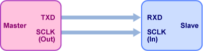
If the set of the data is 8bits, 8 clocks are issued to synchronize the transfer data. The master’s command is transferred to the slave with the clock signal. That means, when the master transmit or receive data to/from the slave, the master starts the transfer request by issuing the clocks. Because the data transfer direction is pre-defined, the master issues clock to the slave when necessary, and perform data transmission or reception to/from the slave, synchronizing with the clock.

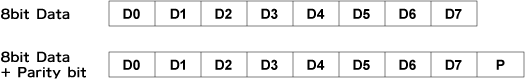
It is common that the data is 8bit serial data. Optionally one parity bit is added at the end of the data, which results in total 9bit long. In this case the slave interface must have already known the serial data has one parity bit before receiving it.
UART (Universal Asynchronous Receiver Transmitter)
UART is asynchronous serial interface, which has no clock signals between two interfaces. So the definition of a master or a slave is meaningless in UART.
Although the purpose of eliminating clock signal is to prevent the noise problems, this will cause another difficulty. As explained before, the command from a master is sent to a slave through a clock signal in SIO. But as UART does not have any clock signal, UART interfaces cannot take any command. Thus, the receiver has to wait for data arrival and then receive the data correctly in any time.
In order for receiver to be able to recognize the beginning and the end of the transfer data, the transmitter should place some indicators of either a start or an end of the data to the transfer data. The start bit is a data “0”, and the stop (end) bit, “1” which are added before and after the transfer data, respectively.
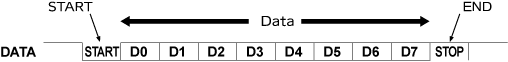
The assignment which one is a transmitter or a receiver has already done before data transfer. If the data line becomes ‘0’ (the data line is usually ‘1’ ), the receiver recognizes the transmitter will send a data and starts to prepare receiving the transfer data. During the data transfer, it is difficult to understand how long (in time) the interval of one bit is, because there is no clock signal. If two ‘0’s (‘00’) are sent from the transmitter, it is not possible for the receiver to identify the transfer data is just one ‘0’ or ‘00’ without any convention between the transmitter and the receiver.
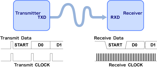
The typical example of the convention is that the receiver receives the data with a clock whose frequency is 16 times faster than the transmitting clock in the transmitter, which should be pre-defined before the data transfer. Once the receiver detects the start bit, it catches the data at every 16 clocks.
A parity bit can be added in UART as well as in SIO.
There may be more than two interfaces in UART. In this case, only one interface should be assigned to be the master and others to be the slaves. And a hand-shake function works on UART by the receiver returning an acknowledge to the transmitter.
SSP (SPI) (Synchronous Serial Port (Serial Peripheral Interface))
SSP is a general term of synchronous serial interfaces, and refers to several different data transfer methods which includes SPI.
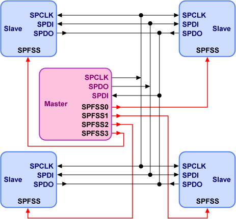
SPI has one master and a plural of slaves, which means it has Star type structure. Two data lines are shared by all interfaces. One of them is master transmitting data line (SPDO) and the other, master receiving data line (SPDI), respectively. By using these two data lines, SPI can make it easy to control slave interfaces and realize a simple method to increase the number of the slave interfaces because no data collisions occur on the data lines. A clock line (SPCLK) is shared by the master and all slaves as well as the data lines.
The master has select lines (SPFSSn) to access one of the slaves to communicate to the master. One select line is connected to one slave, so the master has the same numbers of the select lines as that of the slaves.
I 2 C (Inter-Integrated Circuit)
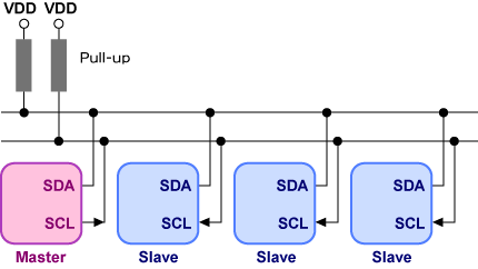
Even though a plural of slaves exist in the network, only two lines, a data line and a clock line, are necessary in I2C. And I2C also permits multi-master structure (more than one master can be assigned). The assignment of a master or a slave is done by setting a register in each interface control circuit. I2C is synchronous interface.
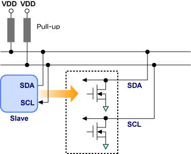
I2C data and clock lines are devised to achieve the multi-master structure. All output from the interfaces are only “0”or High-Z state, and the data and clock’s high level are given by pull-up elements on the lines (wired-AND structure). The output buffer of each interface is just NMOS transistors, no PMOS ones. When necessary, those transistors become ‘on’ and the output of the interface will be “0”. If those NMOS transistors become ‘off’, then the output of the interface become High-Z state. Because the pull-up element is connected to each line, if all the outputs of the interfaces connected to a signal line become High-Z state, then the line is pulled up to VDD and becomes “1”. This is ‘wired-AND’ structure.
Data “0” is ‘stronger’ than data “1” in wired-AND connection. That is, if two interfaces output “0” and “1” (High-Z state) respectively, then the data of the line becomes “0”. This strength priority realizes an arbitration to prevent data collision in multi-master system. Let consider two masters output data to the data line simultaneously. If the one of the data is “0” and the other’s is “1”, the latter interface would know some other outputs “0” now and, on its own judgment, stops the line access immediately. As the result the former keeps the priority to use the line and the latter will resume the data transfer after knowing the end of the data transfer by the former. This kind of arbitration enables the multi-master system.
CAN (Controller Area Network)
CAN is a network which are mainly used to communicate inside an automobile. The structure of CAN is dedicated to noise immunity. It adopts differential data lines architecture without any clock lines. Then, CAN is asynchronous interface although CAN is constructed by only two signal lines like I2C.
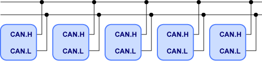
The double data lines are called CAN.H and CAN.L. The voltage differences between two data signals represent the data; both higher voltage CAN.H and lower one CAN.L defines data “0”, and the same voltage level of those signals does data “1”. Those definitions realize high noise-immunity because a noise would affect both lines in the same manner simultaneously.
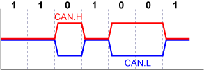
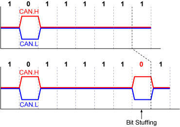
CAN interfaces have a special way to synchronize each other without any clocks and there is no distinction between master and slave. Thus, there is a possibility of data collision on the signal lines and priority should be given to each interface. The synchronization between the interfaces is done as in the following way. First, a transmitter transfers a start bit “0” before sending data. Because the data on the signal lines have been “1” so far, the other interfaces , then, detect this “0” data and synchronize their own clocks to the edge of the data “0”. And while receiving the transferred data, the receiver will adjust its clock timing to the any edge of data “0”. This scheme has a problem when data “1” continues because the data “1” has no edges on CAN.H or CAN.L. The continuous sequence of data “1” occurs no edges and the receiver may become off-synchronization to the transmitter. The solution is ‘bit staffing’ technology, which, in this case, one data “0” is inserted after five continuous “1” data just for synchronization by the transmitter. The receiver uses the data “0” to synchronize its clock and eliminates it from the received data.
As mentioned before, priority should be given to each interface to prevent data collision. For this, each CAN interface has its Identifier (11bits). The Identifier can be used to prioritize each interface to transfer data in order to prevent data collisions.
Actually, when data “0” and data “1” are output from different interfaces to the data lines, data “0” is transferred in CAN like in I2C. After the start bit and before transfer data, a transmitter transfers its own Identifier. When two interfaces transmit their Identifiers at the same time, one of the interfaces will win which outputs “0” while the other, “1”. The former interface can occupy the data lines and complete the transmission before the other.
USB2.0 (Universal Serial Bus 2.0)
USB 2.0 is a very popular serial interface especially for PCs. As well known, USB 2.0 is used in various applications and applied to the interfaces for keyboard, mouse, printer, Flash memory, hard disk drive, speaker, and so on.
USB 2.0 has three speed versions, Low-Speed (1.5Mbps), Full- Speed (12Mbps), and High-Speed (480Mbps). Toshiba TX03 series microprocessors support USB 2.0 Full-Speed.
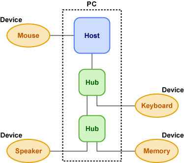
A hierarchical structure is applied to USB interface. In USB, the master is called “Host” and the slave “Device”. USB 2.0 is Star-type network in which one “Host” dominates many “Devices” in it. For example, a PC is a Host, and Devices are any apparatuses which are connected to the PC through USB cables, like a keyboard, a mouse and so on.
USB has a remarkable feature of plug-and-play. Switching off a PC is unnecessary when USB Devices are connected or removed. This is one of the reasons USB has become so popular.
USB Host has to do several works in order for USB Device to be able to be easily connected or removed to/from the network. When a USB Device is connected the network, then the Device send a request to the Host. By receiving the request from the Device, the Host start to obtain the information of the Device, select the most suitable driver, and assign an address to the Device. This operation by the Host is called enumeration. After the successful enumeration, the Host can properly access the Device.
The maximum number of Devices and Hubs controllable by the Host is 127. And if the Hubs are inserted in the network, the number of the Hubs connected in series must be less than or equal to 5.
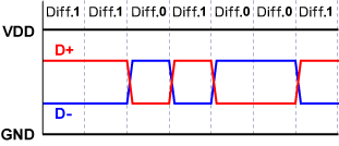
The USB 2.0 cable has 4 wires; VDD, GND, signal D+, and signal D-. The Signals D+ and D- takes complementary values each other for one transferred data. In the case that D+ is high and D- is low, the data is called “Differential 1”. And D+ is low and D- is high, “Differential 0”.
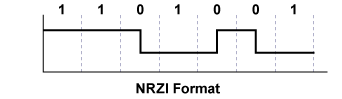
But in the actual data transfer in USB 2.0 network, “Differential 1” and “Differential 0” does not necessarily mean data “1” and data “0”, respectively. The data format of USB is NRZI (non-return to zero inverted). This format defines data “1” when no change occurs in one clock interval, and data “0”, either high-to-low or low-to-high change occurs.
USB 2.0 does not have any clock lines, and so, it is asynchronous interface. So the Host and the Driver have to synchronize each other like in CAN. 8 bit SYNC codes are transferred to synchronize a receiver to a transmitter in USB Full-Speed.
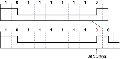
While data transfer, a bit stuffing of data “0” is done after 6 times continuing data “1” in USB 2.0, because no signal edges appear in NRZI format when only data “1s” are transferred continuously.
EtherMAC (Ethernet Media Access Control)
EtherMAC is a part of Ethernet interface. It is not easy to introduce full function of Ethernet because the interface has very complicated structure. This is just a brief explanation regarding Ethernet which will provide overview of differences from other serial interfaces explained so far.
“Ether” of Ethernet comes from a medium called “Aether”, whch was defined by Physics and once supposed to fill all space. The existence of “Aether” is finally denied but because the “Aether” was thought to exist everywhere, it becomes the naming origin of this network.
Ethernet can be mainly divided into four hierarchical layers which are physical layer, data link layer, network layer and the upper layers from the bottom. EtherMAC handles the lowest two layers, physical and data link ones.
An Ethernet cable consists of four signal wires. Two twisted wires are used for output data and another two twisted wires, for input data. This cable has good noise immunity even without electric shield (Unshielded Twisted Pair: UTP). There are no clock lines so Ethernet is an asynchronous interface.
In order to comprehend the concept of Ethernet, 10Base-T is introduced here even though 100Base-TX is the most popular version today because 10Base-T is fundamental and much simpler than 100Base-TX.
10Base-T is an interface which has 10Mbps transfer rate and Baseband format with using a twist pair cable.
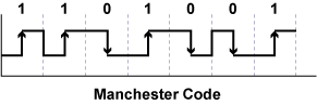
Manchester Code format is applied to the signal transfer. In Manchester Code data “1” and “0” are defined with rise transition and fall one, respectively.
Ethernet does not have any clock lines. A receiver and a transmitter have to synchronize each other, the same as in CAN and USB2.0 interfaces. However, there is no need for bit stuffing even if the same data is repeating continuously because there is signal transition both in data “1” and in data “0”. Instead, the transmitter sends 56 bit continuous pulses preceding data only to synchronize the receiver with the transmitter.
Ethernet has no hierarchy structure such as Host-and-Device relation which is essential in USB2.0. When one unit of the interface would like to output data, the line must be vacant. The unit has to wait if another unit occupies the line. Even though the unit has ensured the line is available and started to transmit data, a collision will occur if one of the other units starts to send data coincidentally. Once the collision occur, all units stop sending their data and wait for the vacancy of the line. And one unit will start but another collision may again occurs because other units would do the same. In order to prevent such permanent collisions, Ethernet has a countermeasure against the collision. When a collision happens, the wait times for the transmitters are determined by random numbers. This is effective for the units which made the collision. But a new unit might make a collision when one of the previous units starts to transmit the data again. The unit can try to send the same data 16 times at a maximum.
This is one of the best arbitration methods in the system without Master-and-Slave relation to share communication responsibility.