- 半導體首頁
-
應用Automotive
Body Electronics
xEV
In-Vehicle Infotainment
Advanced Driver-Assistance Systems (ADAS)
Chassis
IndustrialInfrastructure
BEMS/HEMS
Factory Automation
Commercial Equipment
Consumer/PersonalIoT Equipment
Healthcare
Wearable Device
Mobile
Computer Peripherals
-
產品車用元件
Discrete Semiconductor
Diodes
電晶體
通用邏輯IC
Analog Devices
Digital Devices
Wireless Devices
※
 : Products list (parametric search)功率半導體
※
: Products list (parametric search)隔離器/固態繼電器Photocouplers
Digital Isolators
※
: Products list (parametric search)MOSFETsIGBTs/IEGTs雙極性電晶體※
: Products list (parametric search)Diodes※
: Products list (parametric search)微控制器馬達驅動 ICs智能功率 ICs※
: Products list (parametric search)電源管理 ICs線性 ICs※
: Products list (parametric search)通用邏輯 ICs線性影像感測器其他產品其他產品
※
: Products list (parametric search) -
開發/設計支援
開發 / 設計支援
-
技術知識
- 購買管道


- 型號 & 關鍵字搜尋
- 交叉搜尋
- 參數搜尋
- 線上庫存查詢跟購買
This webpage doesn't work with Internet Explorer. Please use the latest version of Google Chrome, Microsoft Edge, Mozilla Firefox or Safari.
型號需要超過三個文字以上 Search for multiple part numbers fromhere.
The information presented in this cross reference is based on TOSHIBA's selection criteria and should be treated as a suggestion only. Please carefully review the latest versions of all relevant information on the TOSHIBA products, including without limitation data sheets and validate all operating parameters of the TOSHIBA products to ensure that the suggested TOSHIBA products are truly compatible with your design and application.Please note that this cross reference is based on TOSHIBA's estimate of compatibility with other manufacturers' products, based on other manufacturers' published data, at the time the data was collected.TOSHIBA is not responsible for any incorrect or incomplete information. Information is subject to change at any time without notice.
型號需要超過三個文字以上
What is the relationship between transient thermal impedance and safe operating area of bipolar transistors?
Thermal resistance is calculated as a rate of change of temperature caused by a single pulse application with respect to power dissipation. Transient thermal Impedance is a response of a device to a single pulse expressed in terms of the pulse duration. The thermally limited region of the SOA is calculated based on transient thermal resistance.
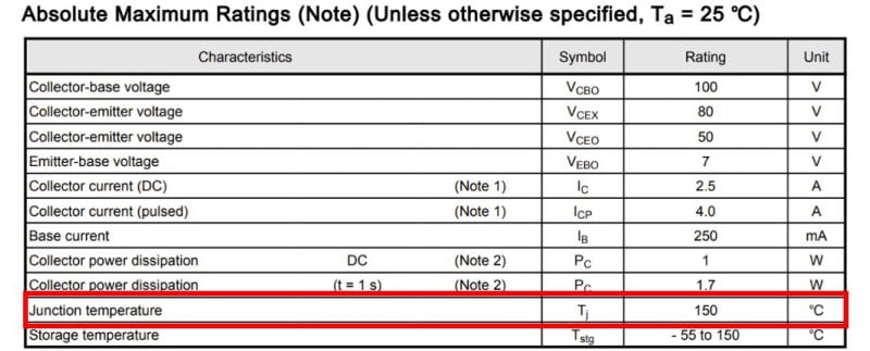
When a current flows through the junction of a semiconductor, the temperature of the junction rises due to the power consumed at the junction. If an excessive current flows, it will deteriorate and break down due to the temperature. For this reason, the junction temperature is specified in the absolute maximum rating of the product data sheet. (Table. 1)
Applying a direct current to a pn junction generates heat. This heat is radiated to the substrate and air via the heat sink, package surface, and leads. As a result, the temperature of the junction begins to rise immediately after the current is applied, but it saturates at a certain temperature.
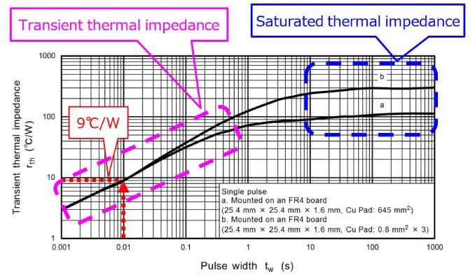
The value obtained by dividing the temperature change by the applied power is the thermal resistance, which indicates the difficulty of heat transfer. When saturated, this value is called saturated thermal resistance (thermal resistance), and the transient value when there is a change is called transient thermal resistance (transient thermal impedance). Fig. 1 is a graph of transient thermal resistance when instantaneous pulse power is applied. Using this, the junction temperature when an instantaneous pulse is applied can be obtained. It can also be used to estimate a rise in junction temperature caused by the application of continuous pulse power.
For details, see the Bipolar Transistor Application Note: Thermal Stability and Thermal Design.
The relationship between junction temperature and the SOA (Safe Operating Area) is shown below.
Tj(max) = rth(j-c) × Po + Ta
From Fig. 1, when the pulse width is 10 ms, The transient thermal resistance is read as:
rth(j-c) = 9 ℃ / W
The peak power that provides the maximum junction temperature (Tj(max)) is calculated as:
150 ℃= 9 ℃ / W*Po + 25 ℃
Po = 125 / 9 = 14 W
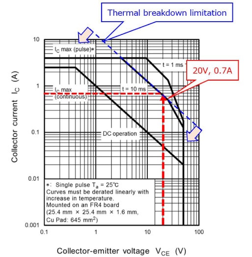
For example, when VCE = 80 V, the allowable current when VCE = 20 V is calculated as:
14 / 20 = 0.7 A
Therefore, in the SOA graph shown in Fig. 2, the region limited by transient thermal resistance is the area bound by a blue dashed line. Bipolar transistors must be used within the region bound by this dashed line so that their junction temperature will not exceed the specified Tj(max).
The SOA region limited by transient thermal resistance is indicated as a thermal breakdown limitation.
相關信息
The following documents also contain related information: