
- 半導體首頁
-
應用Automotive
Body Electronics
xEV
In-Vehicle Infotainment
Advanced Driver-Assistance Systems (ADAS)
Chassis
IndustrialInfrastructure
BEMS/HEMS
Factory Automation
Commercial Equipment
Consumer/PersonalIoT Equipment
Healthcare
Wearable Device
Mobile
Computer Peripherals
-
產品車用元件
Discrete Semiconductor
Diodes
電晶體
通用邏輯IC
Analog Devices
Digital Devices
Wireless Devices
※
 : Products list (parametric search)功率半導體
※
: Products list (parametric search)隔離器/固態繼電器Photocouplers
Digital Isolators
※
: Products list (parametric search)MOSFETsIGBTs/IEGTs雙極性電晶體※
: Products list (parametric search)Diodes※
: Products list (parametric search)微控制器馬達驅動 ICs智能功率 ICs※
: Products list (parametric search)電源管理 ICs線性 ICs※
: Products list (parametric search)通用邏輯 ICs線性影像感測器其他產品其他產品
※
: Products list (parametric search) -
開發/設計支援
開發 / 設計支援
-
技術知識
- 購買管道


- 型號 & 關鍵字搜尋
- 交叉搜尋
- 參數搜尋
- 線上庫存查詢跟購買
This webpage doesn't work with Internet Explorer. Please use the latest version of Google Chrome, Microsoft Edge, Mozilla Firefox or Safari.
型號需要超過三個文字以上 Search for multiple part numbers fromhere.
The information presented in this cross reference is based on TOSHIBA's selection criteria and should be treated as a suggestion only. Please carefully review the latest versions of all relevant information on the TOSHIBA products, including without limitation data sheets and validate all operating parameters of the TOSHIBA products to ensure that the suggested TOSHIBA products are truly compatible with your design and application.Please note that this cross reference is based on TOSHIBA's estimate of compatibility with other manufacturers' products, based on other manufacturers' published data, at the time the data was collected.TOSHIBA is not responsible for any incorrect or incomplete information. Information is subject to change at any time without notice.
型號需要超過三個文字以上
TLCS-870/C1 Series Development System
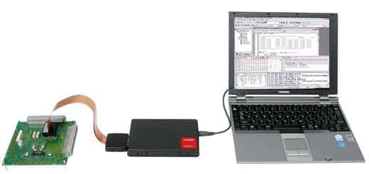
In-Circuit Emulation System
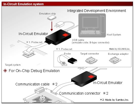
The RTE870/C1 In-Circuit Emulation System consists of Integrated Development Environment, RTE870/C1 In-Circuit Emulator, emulation chip (TMP89C9xxXB:another sales), and Probe set (Note). The component parts of the RTE870/C1 In-Circuit Emulator have been standardized. A target MCU in the TLCS-870/C1 series can be easily changed by replacing only a Probe set and emulation chip.
(Note) Made by ADLINKS,Inc,
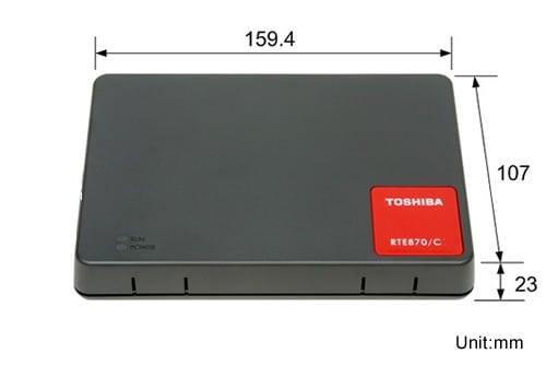
- Small and inexpensive high-performance In-Circuit Emulator.
(Compared with the RTE870/C model 15 emulator) - Affluent Memory Access functions.
- USB connection to the host system.
- Integrated Development Environment included. (Web download right provided)
- Supports on-chip debug emulation.
Check the product names and numbers at this website
The product information is also provided in "Comprehensive List (Microcomputers)" under "Document" for your use.
| Host interface | USB2.0 Full-speed | |
|---|---|---|
| Emulation memory | 128 Kbytes | |
| Event | Number of points | 16 points |
| Comparison items | Address, data, status | |
| Comparison conditionscondition | Match, unmatch, range, mask | |
| Pass count | 1 to 65535 times | |
| Event trigger actions | Break, trace control, timer control, external trigger output, memory write | |
| Event combinations | AND, OR, sequential | |
| Hardware break | 1024 points | |
| Software break | - | |
| Trace memory Capacity | 256 K frames (Notes-1) | |
| Trace memory Modes | Free trace, trigger trace, overwriting prohibit, sampling trace, overflow stop | |
| Trace items | PC address, data address, data value, status, tag timer | |
| Timer measurement | Run timer: 1 channel Lap timer: 4 channels (max., min., average, count) |
|
| Memory access | Memory display during program execution | At fixed intervals: 64 Kbytes At variable intervals: entire RAM area |
| Memory rewrite during program execution | 1 address(byte/word/Long word either) (Notes-2) | |
| Program variables | Display | Binary, octal, decimal or hexadecimal display can be selected for each variable. |
| Registration | Variables, arrays, structures and unions can be registered by the elements. | |
| Sauce display | - Source - Source + assembler code - Source + assembler code + machine language |
|
| External output | 8 lines | |
| External input | - | |
| Performance analysis: Module time measurement | - | |
| Performance analysis: Coverage measurement | C0 coverage | |
| Flash programming/security feature | Supported (in on-chip debug emulation) | |
(Notes-1) There are some cases where the trace memory capacity varies by a tracing condition or operating status.
(Notes-2) Wait of 1 clock cycle per write of 1 byte.
Memory Access
- "Running data display feature"
1.At fixed intervals (IDE feature name "Watch")
Capable of displaying the values of registered variables. The registered variable value display is updated when the target program is stopped, but it is also possible to set to update at constant intervals during program execution.2.At variable intervals (IDE feature name "Memory Dump")
Capable of displaying all memory contents at variable intervals while running program. The time of reading RAM data might vary by a range of address (number of data) and contents of program. - "Running data rewrite feature" (IDE feature name "Tuning")
Capable of freely changing the contents of the memory without requiring a user to stop a program while running it. Changeable areas include MCU's I/O area and built-in RAM area. This allows you to adjust program operation by every parameter value change.
(Note) Wait of 1 clock cycle per write of 1 byte.
Event comparison/trace memory storage of write operation via stack pointer
Capable of setting data-writing via a stack point as an event comparison target to generate a trigger. By applying this, it is also capable of storing into the trace memory only the data written via the stack pointer. By detecting data-writing to an address other than a pre-assumed stack area, this feature allows you to debug program failures caused by an excessive stack.
Product Configuration and Appearance of In-Circuit Emulator
Content of Product
- RTE870/C1 In-Circuit Emulator main body
- Communication cable for On-Chip Debug Emulation (Note)
- Communication connector for On-Chip Debug Emulation (Note)
- One license for downloading the Integrated Development Environment from website.
(Note) Made by Samtec,Inc.
Items to Be Prepared by Customer
For In-Circuit Emulation
- Host system
- USB cable (emulator side: B-type connector)
- Probe set (Note)
- Emulation chip
- AC power supply adaptor
(Note) A probe set is a product combining a Probe , a Exchange adaptor and a Target connector for each supported MCU.
For On-Chip Debug Emulation
- Host system
- USB cable (emulator side: B-type connector)
- AC power supply adaptor
- Microcomputer on the target system (with on-chip debug function incorporated)
(Notes-1) The on-chip debug function uses two pins for communications (OCDCK, OCDIO) and four pins for monitor signals (VDD, GND, RESET, MODE).
When the On-Chip Debug Emulator is connected to the target system, the OCDCK and OCDIO pins are used exclusively by the Emulator and cannot be used as port pins (P20, P21) or UART0/SIO0 pins.
(Notes-2) For the operation assurance range and characteristics of the supplied power/clock, see the microcomputer's datasheet.
About AC power supply adaptor
If you are using this product, use an AC adapter and an AC cable that are compliant with the safety standards of your country or region.
AC adapter compliance specifications
Output voltage: 9[V]
Output current: 1[A] or larger
Example Part Number: A10P1-09MP (AKII TECHNOLOGY CO., LTD.)
The DC plug of the AC adapter should have the following outer dimensions and polarity. Not satisfying these requirements will cause malfunction.
About Emulation Operating Voltage/Frequency
For In-Circuit Emulation
- The RTE870/C1 In-Circuit Emulator does not support emulation by clock on the target system. It is used the clock on the emulator for emulation.
- If the emulator power (system power) is selected as the emulation power, the emulation supply voltage will be 5 V +/- 5%.
- Note that the power/clock cannot be supplied from the emulator to the target system.
For On-Chip Debug Emulation
- To use all the on-chip debug functions offered by this Emulator, the target system must be operating within the target MCU's guaranteed operating voltage range for FLASH program and erase operations. The load (FLASH program) function using this Emulator cannot be guaranteed outside this voltage range.
For the guaranteed operating voltage range for FLASH program and erase operations, see the microcomputer’s datasheet. - If the Emulator is to be used outside the guaranteed FLASH program/erase operating voltage range and the MCU's guaranteed operating voltage range, the FLASH memory must be programmed with a programming tool prior to using the Emulator.
- Any operating frequency in the device operation assurance range is available.
- Note that the power/clock cannot be supplied from the emulator to the target system.
Precautions for USB Connection
- The emulator is connected to the host system via the USB. (USB2.0 Full-speed)
- To newly connect the emulator to the host system, it is necessary to install a USB driver.
- Depending on the USB's destination (host system), a protocol error may occur on rare occasions. If this error occurs, replace the USB connection cable with the following. Recommended cable: 0.7 m or longer USB cable with ferrite cores attached to its both ends
Accessory
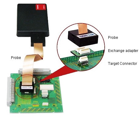
A probe (*1) and a target connector (*1) are used for connecting an emulator to a target system. An exchange adapter (*1) may be required depending on the debug target MCU. They are marketed as a probe set (*1). Use a stacking adapter (*1) and an MCU mounting adapter (*1) as required.
*1: They are made by ADLINKS. See ADLINKS Co., Ltd.'s website.
Probe
A probe is used to connect an emulator with a target system. There are different probes depending on the numbers of pins on a package, package types, and different probe sets depending on the supported MCU. The probe sets are manufactured by ADLINKS Co., Ltd. For information about the specification of the probe, please refer to ADLINKS Co., Ltd's website.
Target Connector
To connect the emulator to the target system, solder the target connector to the MCU mounting area on the target system.
For the product specifications of the target connector and the recommended footprints, see ADLINKS Co., Ltd.'s website.
Exchange adapter
The exchange adapter converts the number of pins and pin layout according to the specifications of the supported MCU. If a corresponding probe set contains the exchange adapter, remember to use it.
For information about the specification of the exchange adapter, please refer to ADLINKS Co., Ltd's website.
Stacking adapter
This stacking adapter is used between the probe and the target connector to adjust height in case such parts around the footprint on the target board are difficult to connect to the target system. It raises height and provides easy connection. For information about the specification of the stacking adapter, please refer to ADLINKS Co., Ltd's website.
MCU mounting adapter
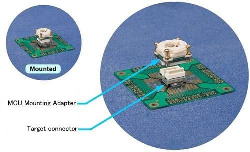
The MCU mounting adapter (Bump socket) is used, together with the target connector, to mount an MCU on the target system. The MCU mounting adapter for the 870/C Light system is manufactured by ADLINKS Co., Ltd. For information about the specification of this product, please refer to ADLINKS Co., Ltd’s website.