
- 半導體首頁
-
應用Automotive
Body Electronics
xEV
In-Vehicle Infotainment
Advanced Driver-Assistance Systems (ADAS)
Chassis
IndustrialInfrastructure
BEMS/HEMS
Factory Automation
Commercial Equipment
Consumer/PersonalIoT Equipment
Healthcare
Wearable Device
Mobile
Computer Peripherals
-
產品車用元件
Discrete Semiconductor
Diodes
電晶體
通用邏輯IC
Analog Devices
Digital Devices
Wireless Devices
※
 : Products list (parametric search)功率半導體
※
: Products list (parametric search)隔離器/固態繼電器Photocouplers
Digital Isolators
※
: Products list (parametric search)MOSFETsIGBTs/IEGTs雙極性電晶體※
: Products list (parametric search)Diodes※
: Products list (parametric search)微控制器馬達驅動 ICs智能功率 ICs※
: Products list (parametric search)電源管理 ICs線性 ICs※
: Products list (parametric search)通用邏輯 ICs線性影像感測器其他產品其他產品
※
: Products list (parametric search) -
開發/設計支援
開發 / 設計支援
-
技術知識
- 購買管道


- 型號 & 關鍵字搜尋
- 交叉搜尋
- 參數搜尋
- 線上庫存查詢跟購買
This webpage doesn't work with Internet Explorer. Please use the latest version of Google Chrome, Microsoft Edge, Mozilla Firefox or Safari.
型號需要超過三個文字以上 Search for multiple part numbers fromhere.
The information presented in this cross reference is based on TOSHIBA's selection criteria and should be treated as a suggestion only. Please carefully review the latest versions of all relevant information on the TOSHIBA products, including without limitation data sheets and validate all operating parameters of the TOSHIBA products to ensure that the suggested TOSHIBA products are truly compatible with your design and application.Please note that this cross reference is based on TOSHIBA's estimate of compatibility with other manufacturers' products, based on other manufacturers' published data, at the time the data was collected.TOSHIBA is not responsible for any incorrect or incomplete information. Information is subject to change at any time without notice.
型號需要超過三個文字以上
Why are voltage followers prone to oscillation?
Operational amplifier (op-amp) amplification circuits commonly utilize negative feedback. However, op-amps have a pole (transition point) that can cause phase lag within the bandwidth, resulting in positive feedback. On the other hand, voltage followers (unity gain amplifiers) employ full feedback, and their bandwidth extends up to the cutoff frequency, making them prone to oscillation. When using voltage followers, it is essential to select products that operate at unity gain.
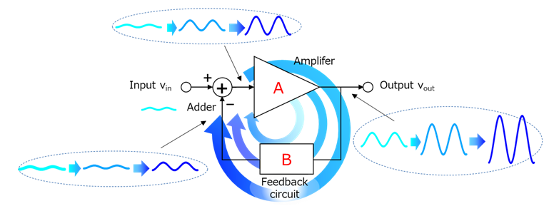
In amplification circuits using operational amplifiers (op-amps), feedback loops are commonly employed. However, under certain conditions, these feedback loops can lead to oscillation. This phenomenon is known as the oscillation condition and is characterized by gain and phase criteria. To put it simply, oscillation occurs when the input signal or noise, as shown in the diagram, is gradually amplified through feedback (see Fig. 1).
Mathematically, this can be expressed as follows:
β x A ≧ 1
∠ β x A ≧ 360°
In other words, oscillation occurs when a signal greater than the original input is fed back and added in phase.
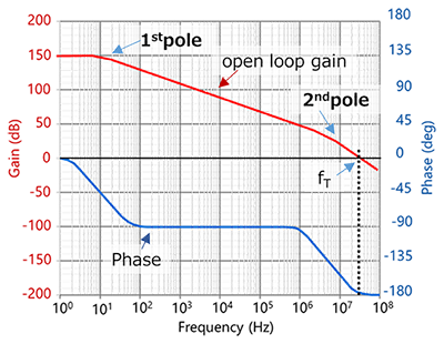
Let’s illustrate the frequency characteristics of a standalone operational amplifier (op-amp) using a graph.
Gain Curve and Poles:
- The gain curve of an op-amp exhibits poles (transition points).
- From the first pole frequency, the gain decreases with a slope of -20 dB/decade.
- If there are two poles, the second pole frequency results in a steeper slope of -40 dB/decade.
- Additionally, the phase shift at this pole frequency is delayed by 90° for a single pole.
- With two poles, the total phase shift amounts to 180°.
Unity Gain and Phase Shift:
- In commonly used op-amps not designed for unity gain operation, there are two gain poles within the bandwidth up to the cutoff frequency (zero-crossing frequency) (f_T).
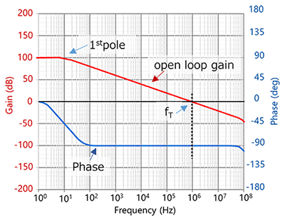
- However, op-amps specifically designed for unity gain operation typically have only one pole within the bandwidth.
- Consequently, the phase shift is limited to 90°.
These characteristics are essential for understanding op-amp behavior, especially when designing feedback circuits. The unity gain frequency and phase shift play crucial roles in determining the usable frequency range of an op-amp circuit.
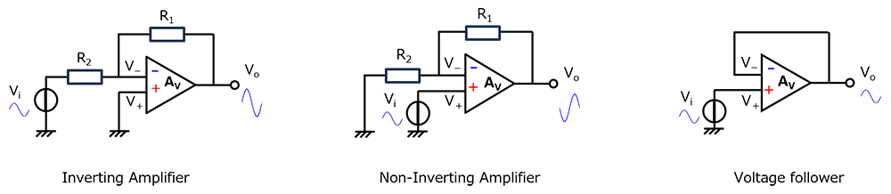
Operational amplifiers (op-amps) are commonly used in two main types of amplification circuits: inverting amplifiers and non-inverting amplifiers. The voltage follower, also known as a unity gain amplifier, falls into the category of non-inverting amplifiers. In a voltage follower, the gain of the non-inverting amplifier is set to 0 dB (with (R_1 = 0) and (R_2 = ∞)).
Here’s how these two types of amplifiers work:
Non-Inverting Amplifier:
- In a non-inverting amplifier, the input is applied to the positive terminal, and feedback is taken from the negative terminal.
- Since the input is connected to the positive side of the op-amp, the phase starts at 0° (similar to the frequency response of a standalone op-amp).
- As the frequency increases, the phase shift progresses from 0° to +180°.
Inverting Amplifier:
- In an inverting amplifier, the input is applied to the negative terminal, and feedback is taken from the output.
The phase shift in an inverting amplifier starts at +180° and decreases as the frequency increases.
The voltage follower is a full feedback non-inverting amplifier circuit with a feedback rate of 100%. It has a band with a gain of 0dB and a cutoff frequency fT. Since the output is fed back to the negative terminal to form negative feedback, if the phase is delayed by 180° within the band, positive feedback will occur at that frequency and oscillation will occur.
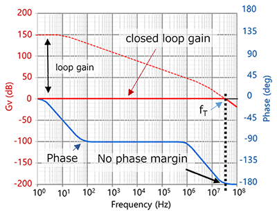
The phase of a voltage follower for an operational amplifier that does not guarantee unity gain and an operational amplifier that does guarantee unity gain is as follows. The phase lag is greatest at the cutoff frequency, for example in the figure below (Fig. 5), it is close to -180°, and there is almost no phase margin. (Depending on the product, it may be zero.)
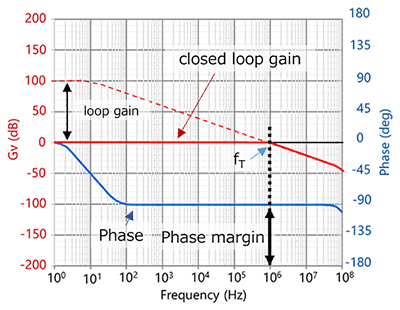
On the other hand, products with a guaranteed unity gain have a phase margin of 90°. (Fig. 6)
However, this is the situation when there is no capacitive load. In reality, there is an output capacitance of the operational amplifier, stray capacitance of wiring, and capacitance on the load side, so further phase lag may occur. Therefore, it can be said that there is a high possibility of oscillation occurring in products that do not have a guarantee of unity gain.
Even products that guarantee unity gain may oscillate if the load capacitance is large, if the cutoff frequency of the LPF consisting of the load capacitance and output impedance is lower than the operational amplifier's fT, or if it is located nearby.
Related Links
FAQs
e-learning
Application Notes
The following documents also contain related information.


Company names, product names, and service names used in this FAQ may be of their respective companies.