

 : Products list (parametric search)


Model-Based Development (MBD) initiatives for automotive semiconductor products
The environment surrounding automotive semiconductors
As automotive electrification and advanced functionalities continue to evolve, in-vehicle systems are becoming larger and more complex. With the integration of diverse electronic components, including power semiconductors, the workload required to ensure safety and reliability is rapidly increasing. At the same time, there is strong pressure to shorten development timelines. As a result, it is becoming difficult to adequately evaluate entire systems within limited resources.
Furthermore, if a defect in a single component is discovered in the later stages of development, it can lead to significant rework for both system manufacturers and component suppliers, resulting in increased development time and costs.
To address these challenges, Model-Based Development (MBD)—a methodology that uses models and simulations to verify systems from the early stages of design—is being rapidly adopted across the automotive industry.
Overview of Model-Based Design initiatives for automotive semiconductors
Considering our role in realizing MBD, firstly, it is required to provide models that operate in the design environment for our customers, the set makers and unit makers. As a concrete initiative, we provide device models such as SPICE models and thermal analysis models that are compatible with various tools in the customer's design environment. In the system-level upper design stages, automotive semiconductors are often treated as ideal semiconductors, and there is a gap in model granularity between the MBD conducted by upstream set makers and unit makers and the MBD by downstream component makers. For example, in the hard verification stage, cases where heat and noise from power semiconductors handling high voltage and large current affect the system are common and pose a challenge. To address this issue, we propose an analysis methodology based on a proprietary Reduced Order Modeling (ROM) technique, which enables thermal design and EMI (electromagnetic interference) noise verification for automotive power MOSFETs and ICs.
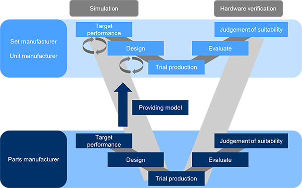
The overall picture of automotive semiconductor models
The following table shows the automotive semiconductor models available from our company.
| Automotive semiconductor model | Electric model | Thermal analysis model |
||||||
|---|---|---|---|---|---|---|---|---|
| Tools/Format | PSpice® | LTspice® | SIMetrix | Eldo™ | PLECS® | Xpedition AMS | STEP | |
| Discrete semiconductor | ◎ | ◎ | ◎ | ◎ | ◎*1 | ○ | ◎*2 | |
| IC | Motor driver | ◎*1 | - | - | - | - | ○ | ○*3 |
| IPD (Intelligent Power Device) |
◎*1 | - | - | - | - | - | ○*3 | |
| Automotive Communication IC (CXPI) |
- | - | - | - | - | ○ | ○*3 | |
◎; Available and now open to the public
〇; Available, Inquiry required
*1; Partially available
*2; A simplified CFD model for thermal analysis is now available on the web, and detailed models are available upon inquiry.
*3; Detailed models are available upon inquiry.
Toshiba's automotive semiconductor models
1. Discrete semiconductor models
As for the electrical models of automotive discrete semiconductor products, we have prepared two types of SPICE models with different granularities. One is the G0 model, which is suitable for function checks due to its fast calculation speed. The other is our proprietary G2 model (high-precision SPICE model) developed for MOSFET products. The G2 model is created in a macro-model format based on BSIM3, using the least possible number of elements and nonlinear elements with continuous arbitrary functions to represent the electrical characteristics of the target elements. As a result, it has features such as minimizing the increase in node count that leads to convergence issues and slower calculation speeds, which are disadvantages of traditional macro models. Furthermore, it excels in reproducing the high-current region characteristics of the ID-VDS curve and the capacitance characteristics with nonlinearity, enabling highly accurate simulations close to actual measurements. It also considers the parasitic elements of the package, allowing for the analysis of ringing and EMI that occur during switching. Please refer to the application notes below for more detailed information.
Automotive Discrete Semiconductor MBD Introductory (PDF: 1.49MB)
The G2 model (high-precision SPICE model) is introduced in the link below.
High accurate SPICE models that can more accurately simulate the transient characteristics of power devices
We provide SPICE models compatible with various simulation tools. Specifically, in addition to the models for PSpice® and LTspice® shown in the table, SIMetrix, Eldo™, and PLECS® models are also available online. The various models can be checked from the link below
EDA/CAD Model Library
Details of the simplified CFD model for thermal analysis of discrete semiconductor products are introduced in the link below.
Cooling simulation model: Expanding the number of Simplified CFD Models for three-dimensional thermal fluid analysis in MOSFETs
We introduce a technology for generating a "concept SPICE model" that enables pre-fabrication prediction of power semiconductor characteristics by combining electrical characteristics extracted from device simulation tools with conceptual design data.
2. IC Models
Introduction of Functional Verification, Thermal Analysis, EMC Analysis, and Control Analysis using IC models. For inquiries and considerations regarding each analysis model, please contact us at the link at the bottom of the inquiry page.
Functional Verification
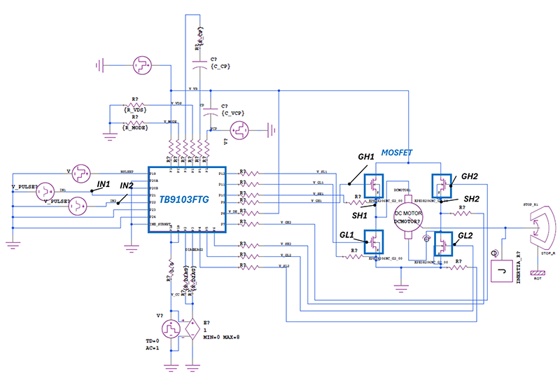
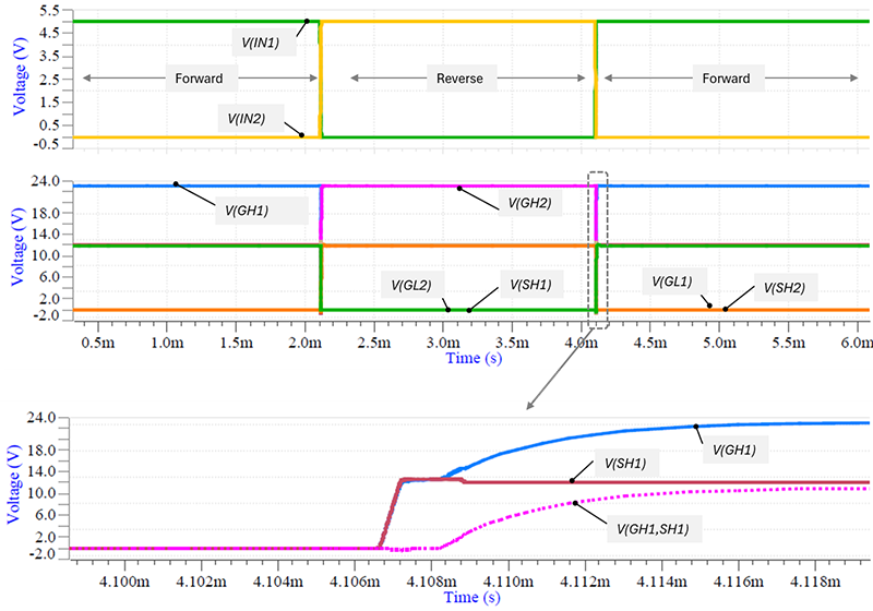
Toshiba is focused on developing new IC products for automotive motor systems and automotive communication systems. Figure 1 is an example of a simulation using Xpedition AMS, which combines the model of the H-bridge gate driver IC (TB9103FTG) with power MOSFET (G2) models and mechanical models such as motors. Figure 2 monitors the voltage applied to each MOSFET driven by a control signal that repeatedly reverses and inverts at the IC's input terminals (IN1, IN2). The lower part of Figure 2 shows an enlarged view of the gate voltage (V(GH1)) and source voltage (V(SH1)) of the high-side MOSFET during the dashed period. With this IC model, it is possible to closely observe the operation of the IC and the behavior of the MOSFET during driving.
Thermal Analysis
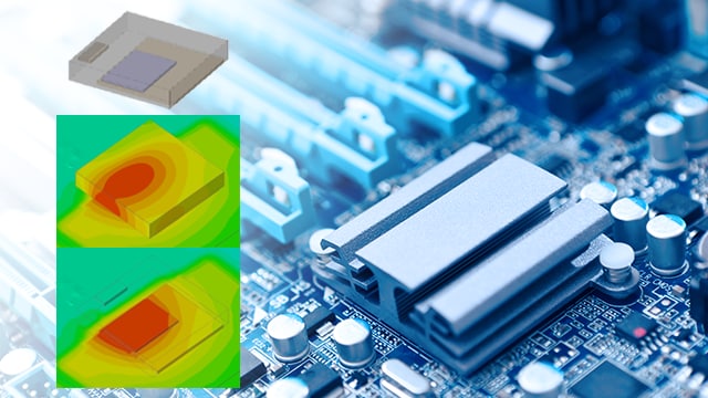
In automotive electronics, the operating environment is becoming increasingly harsh with high-density mounting and high ambient temperatures, leading to various thermal issues due to the impact of electronic components used, their placement, and PCB design. To prevent these issues proactively, it is becoming necessary to perform thermal analysis in the early stages of development. Our company provides detailed models in STEP format for thermal analysis of ICs. Please contact us for the use of models, including products not listed.
| Category | Product | Features | Package | Thermal model |
|---|---|---|---|---|
| CXPI | TB9032FNG | CXPI driver receiver | SOP | STEP formats |
| Brushed Motor Driver | TB9051FTG | H-Brigde driver (1ch) | QFN | |
| TB9052FNG | DC brushed motor GATE-driver (1ch) | SOP | ||
| TB9053FTG | H-Bridge driver (2ch) | QFN | ||
| TB9054FTG | H-Bridge driver (2ch) | QFN | ||
| TB9056FNG | H-Bridge driver with LIN (1ch) | SOP | ||
| TB9057FG | DC brushed motor GATE-driver (1ch) | QFP | ||
| TB9058FNG | H-Bridge driver with LIN (1ch) | SOP | ||
| Brushless Motor Driver | TB9061AFNG | 3-phase sensorless motor GATE-driver | SOP | |
| TB9080FG | 3-phase brushless motor GATE-driver (Built-in control logic that output sine wave drive) |
QFP | ||
| TB9081FG | 3-phase brushless motor GATE-driver | QFP | ||
| TB9083FTG | 3-phase brushless motor GATE-driver | QFN | ||
| Stepping Motor Driver | TB9120AFTG | 2-phase bipolar stepping motor driver (Excitation mode: up to 1/32) |
QFN | |
| SmartMCD™ | TB9M003FG | 3-phase brushless motor GATE-driver | QFP |
* The STEP format is an ISO standard and is compatible with many 3D CAD tools, allowing for use in various fluid analysis tools such as Flotherm™ and Icepak™.
EMC Analysis
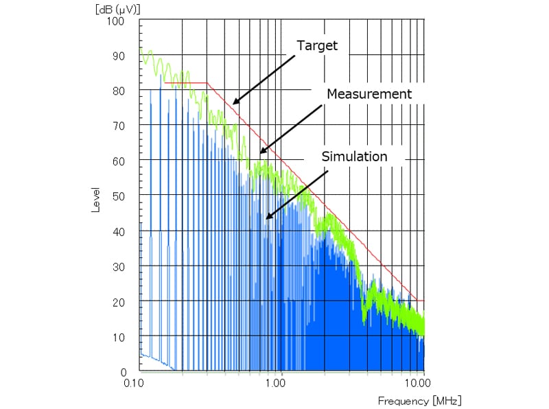
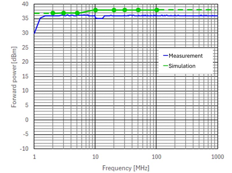
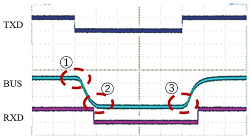
With the advancement of autonomous driving and the increased functionality of each system, the amount of information in vehicle communication networks is growing. In such an environment, EMC (Electromagnetic compatibility) measures to ensure safety and reliability are becoming increasingly essential. However, designing automotive systems that take into account the effects of mutual interference between devices in the complex electromagnetic environment inside a vehicle is extremely challenging. Our company is working on model development and improvement aimed at realizing front-loading of EMC.
Control Analysis
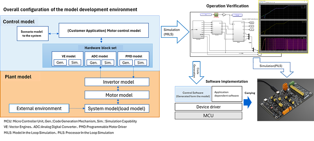
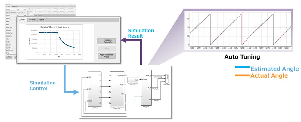
Our company provides a HW block set that realizes SmartMCD™ hardware functions on MATLAB®/Simulink®, and a model for speed control utilizing hardware functions, enabling motor control development using SmartMCD™ without the need for actual hardware (Figure 5). By simulating our control model in combination with a motor model and a load model, you can evaluate system control using SmartMCD™. We are also preparing an automatic generation function for software that can be coupled with hardware-dependent device drivers from the control model. The automatic code generation function allows for easy transition of the evaluated model to actual hardware. Also, an automatic control gain tuning tool using the model is currently under development (Figure 6). Model-based development is realized through control evaluation and calibration with model simulations, and coordination with actual hardware through automatic code generation, reducing the development process.
相關信息


* PSpice®is a trademark of Cadence Design Systems, Inc.
* LTspice® is a simulation software and trademark of Analog Devices, Inc.
* SIMetrix is a simulation software of SIMetrix Technologies Ltd.
* Xpedition AMS is a system simulator of Siemens Industry Software Inc.
* MATLAB®/Simulink® is a simulation software and trademark of MathWorks, Inc.
* VenetDCP® is a trademark of Toshiba Digital Solutions Corporation.
* SmartMCD™ is a trademark of Toshiba Electronic Devices & Storage Corporation.
* Eldo™ is a simulation software and trademark of Siemens Industry Software Inc.
* Flotherm™ is a simulation software and trademark of Siemens Industry Software Inc.
* Icepak™ is a simulation software and trademark of Ansys, Inc.
* Other company names, product names, and service names may be trademarks of their respective companies.